B-Pillar - Master Section Development
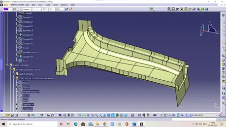
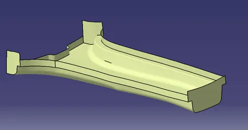
AIM: To create B-pillar trim of a car using class A surface and as well as using the master sections provided by following all the OEM design standards.
SOFTWARE USED: CatiaV5.
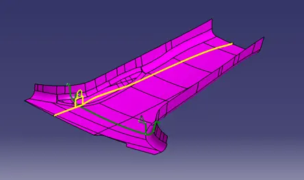
MASTER SECTION PROVIDED:
ABSTRACT:
The design and development of an automobile is a complex process. The Automobile consists of number of parts; among them the important ones are structural elements which form the major skeleton/structure of the Automobile. These elements need to be designed, developed and analysed with at most care, as many other parts are assembled on them. Automobile with major panels welded together is called BODY IN WHITE or BLUE BUCK. This consists of number of panels, one among them is B-PILLAR. This is a structural member as the sides of windshield on which doors will be mounted. This project work involves the surface modelling of B-PILLAR using CATIA, the pre-processing is done in HYPERMESH and analysis of B-PILLAR using different materials in ABAQUS software’s.
OBJECTIVE:
1.To make best use of material by arranging for each member to support as near as possible to its maximum load potential.
2.To make structure direct and continuous by providing an unbroken path from the point of application to point of reaction.
CLASS A SURFACE:
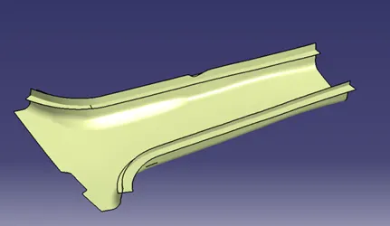
‘A' Class surfacing and its importance: A class surfaces are those aesthetic/ free form surfaces, which are visible to us (interior/exterior), having an optimal aesthetic shape and high surface quality. Mathematically class A surface are those surfaces which are curvature continuous while providing the simplest mathematical representation needed for the desired shape/form and does not have any undesirable waviness. Products are not only designed considering the functionality but special consideration is given to its form/aesthetics which can bring a desire in one’s mind to own that product. This is only possible with high-class finish and good forms. This is the reason why in design industries Class A surface are given more importance.
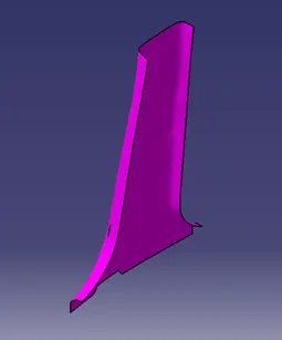
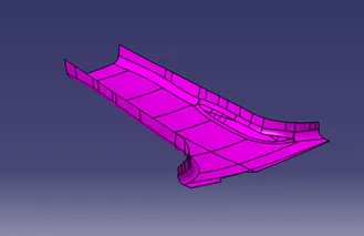
In automotive design, a class A surface is any of a set of freeform surfaces of high efficiency and quality. Although, strictly, it is nothing more than saying the surfaces have curvature and tangency alignment – to ideal aesthetical reflection quality, many people interpret class A surfaces to have G2 (or even G3) curvature continuity to one another (see free form surface modelling). Class A surfacing is done using computer-aided industrial design applications. Class A surface modelers are also called "digital sculptors" in the industry. Industrial designers develop their design styling through the A-Surface, the physical surface the end user can feel, touch, see etc.
CLASS B SURFACE:
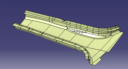
1.Invisible Surfaces.
2.Surface mostly don't have textures
3.Surface need to be created according to class-A surface.
4.Having all features (Rib, boss, snap etc.) in B-side surface only.
5.Surfaces which is having TANGENT CONTINUITY IS CALLED class-B.
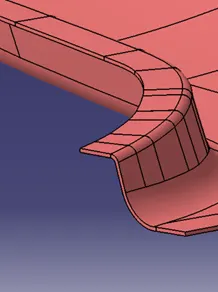
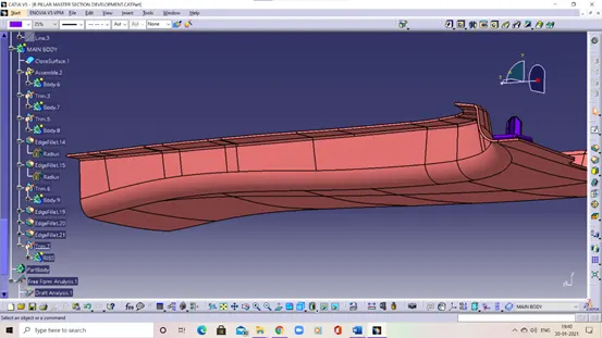
JUST OFFSET THE A SURFACE TO NOMINAL THICKNESS TO OBTAIN B SURFACE.
And then trim it with the flanges created.
C SURFACE:
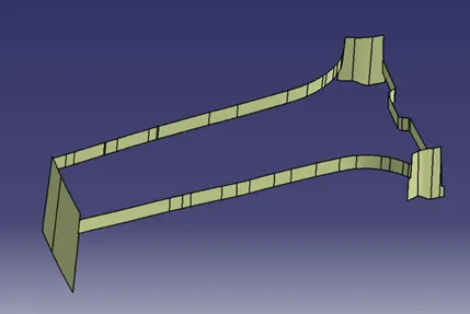
Class C surface is normally created using the sweep command.
First the boundary is extracted and it is made smooth using curve smooth command and then it is sweeped by giving 0.5 draft outwards.
Normally the C surface is nothing but adding thickness or filling the gap between the A surface and B surface.
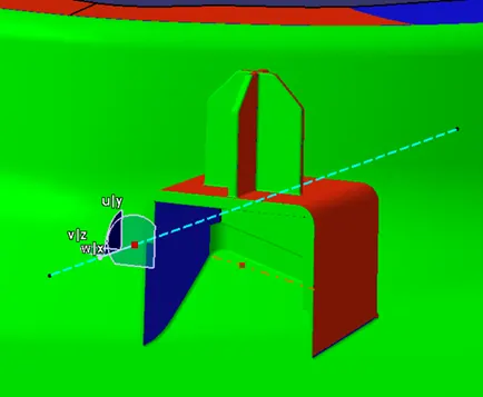
DOG HOUSE (WITH 4 WAY LOCATOR):
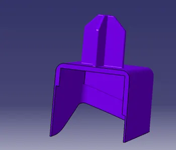
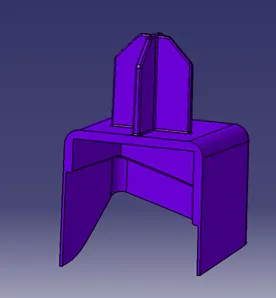
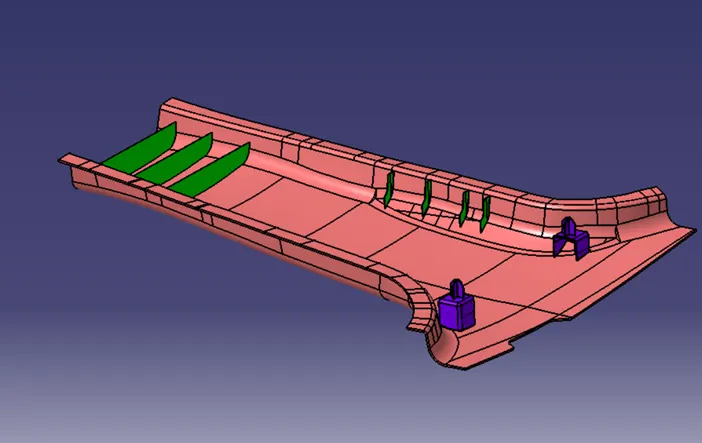
Dog house is an engineering feature used in plastic trim design. Dog houses are used as supporting feature. Sometimes other engineering features like snaps; locators etc. are mounded on them to increase their strength. Dog houses are subjected to draft analysis to prevent breakage of the component during ejection from mould cavity. Dog house and other engineering components are built on B-surface.
RIBS:
Ribs are a feature in plastic injection molded parts. They are thin extensions that run perpendicular from a wall or plane. They are commonly used to provide additional support and strength to a part.
Thickness and location are essential to rib design. Here are some helpful design guidelines:
1.They should be designed with a thickness that is ½ the wall thickness to avoid a thick section at the wall base
2.To minimize sink marks, design ribs that are approximately 60% of the joining wall thickness for minimum risk
3.Best practices include spacing at a distance of at least twice the wall thickness
4.Glossy materials require a thinner rib (40% of wall thickness)

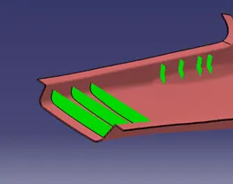
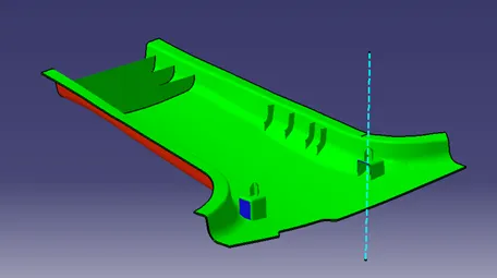
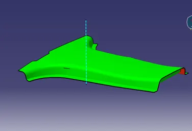
DRAFT ANALYSIS:
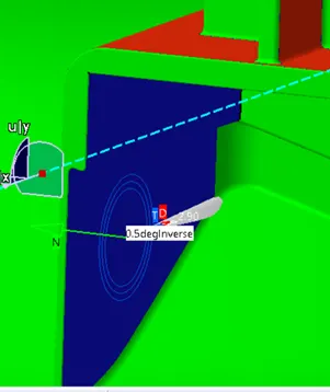
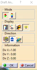
COMMANDS USED:
1.EXTRACT
2.MULTIPLE EXTRACT
3.SWEEP
4.INTERSECT
5.JOIN
6.MULTISECTION
7.TRIM
8.BLEND
9.CURVE SMOOTH
10.OFFSET
11.EXTRAPOLATE
12.SPLIT
13.EXTRUDE
AND ALL THE NESCESSARY SURFACE WORK BENCH COMMANDS.
FINAL OUTPUT:
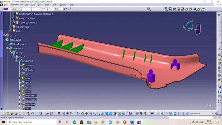
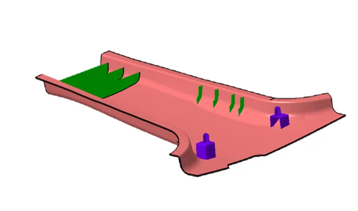
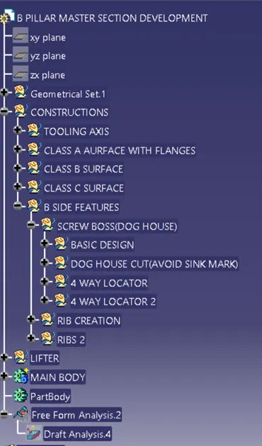
TREE STRUCTURE:
CONCLUSION:
The B pillar trim of the car has been created using the master section development and following all the design standards.