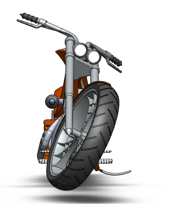
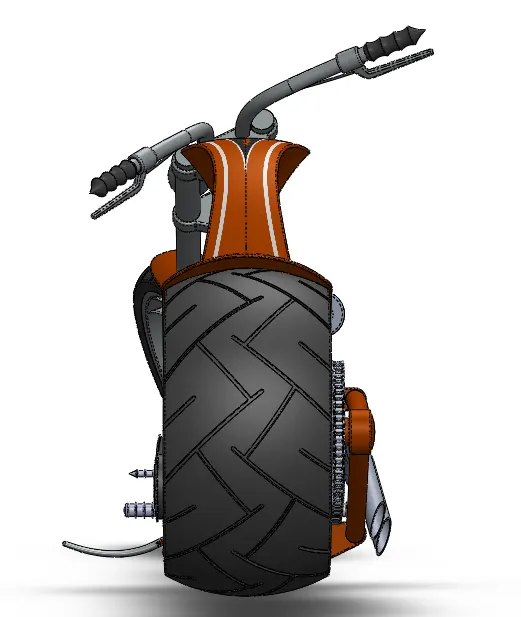
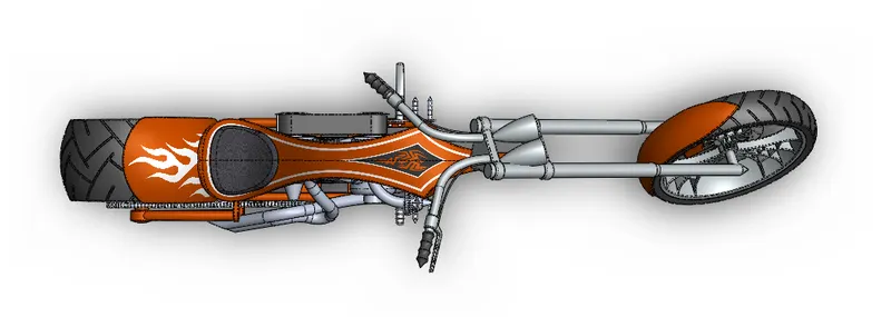
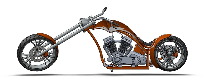
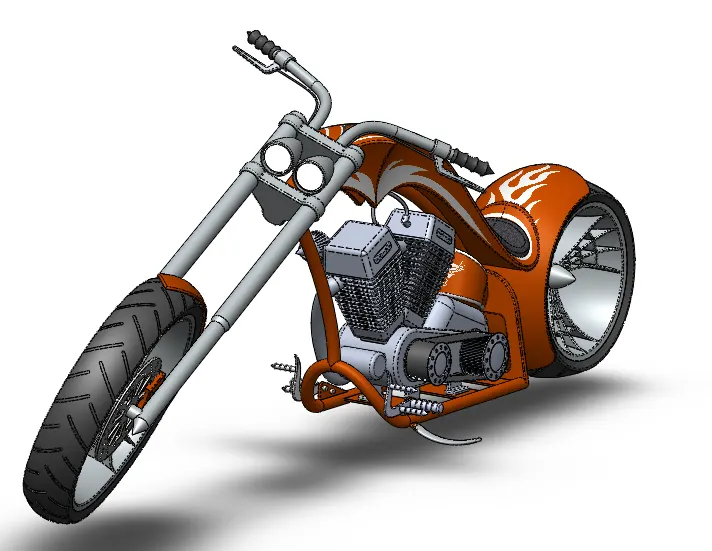
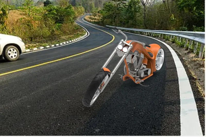
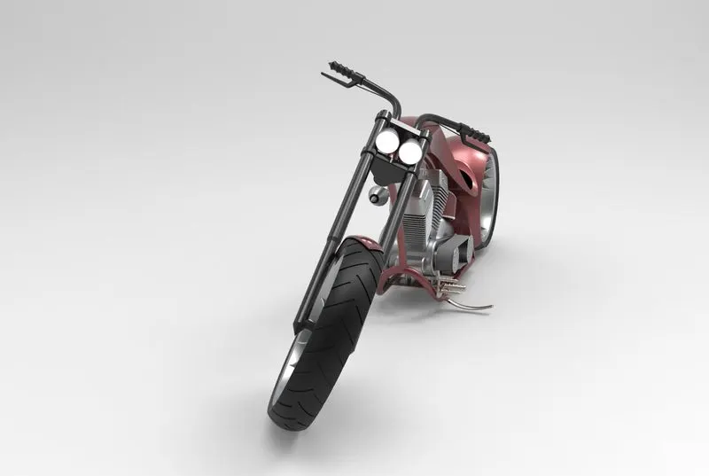
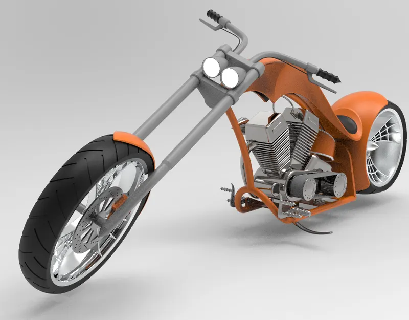
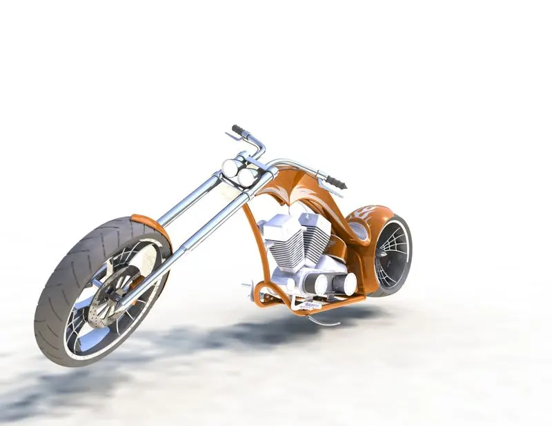
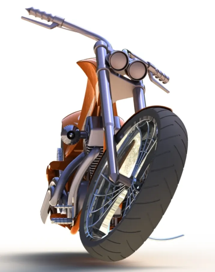
Assembly of American chopper
AIM:
1. To design all the parts of the American chopper using solid works part workbench.
2. To assemble all the parts designed using an assembly workbench following a bottom-up or top-down approach.
3. To create a photorealistic photo rendering using solid works visualize and photo view 360.
OBJECTIVE:
To get familiar with part workbench commands.
INTRODUCTION:
a)Part modeling:
Part modeling is the process of creating a virtual prototype of something by modeling each part separately, which can then all be assembled to create the model of the final product. Think of all of the different parts of a car engine for example.
b)Assembly:
You can build complex assemblies consisting of many components, which can be parts or other assemblies, called subassemblies. For most operations, the behavior of components is the same for both types. Adding a component to an assembly creates a link between the assembly and the component. When SOLIDWORKS opens the assembly, it finds the component file to show it in the assembly. Changes in the component are automatically reflected in the assembly.
The document name extension for assemblies is .sldasm.
Top-down approach:
Top-down assembly modeling is an assembly-centric modeling method where the assembly design is started at the highest level possible, and individual parts and subassemblies are defined within the context of the overall assembly. With this approach, an assembly layout is typically created first, and this assembly layout is used to define individual part geometry and position.
This approach is often used at companies where the product being designed is large enough that it requires many people to complete the design. A senior-level designer might create the initial assembly layout, then divide the assembly layout into logical subassemblies and parts for the remainder of the organization to complete.
Bottom-up approach:
Bottom-up assembly modeling is a part-centric modeling method where the assembly design is started with a principal structural or functional element, and individual parts are designed in relative isolation from the overall assembly. Parts and subassemblies are defined as the process moves up towards the top-level assembly. With this approach, as the design of a key component is completed, its geometry may or may not be used to aid the design of related mating components.
This approach is often used at companies where the product being designed is small enough that one or only a few people are needed to complete the design.
Design Methodology:
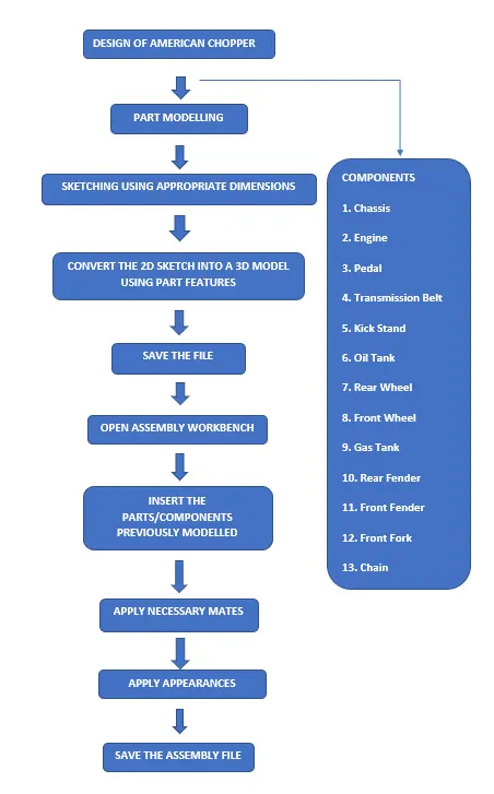
Components of American Chopper:
1. Chassis
2. Engine
3. Pedal
4. Transmission Belt
5. Kick Stand
6. Oil Tank
7. Rear Wheel
8. Front Wheel
9. Gas Tank
10. Rear Fender
11. Front Fender
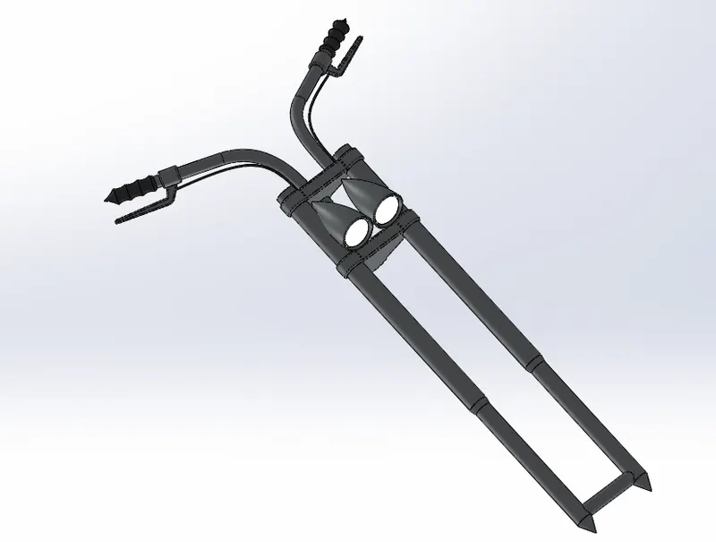
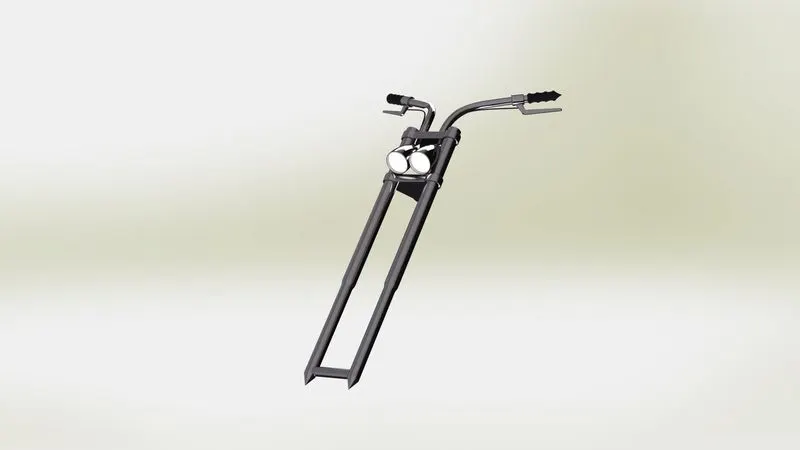
12. Front Fork
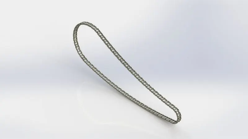
13. Chain
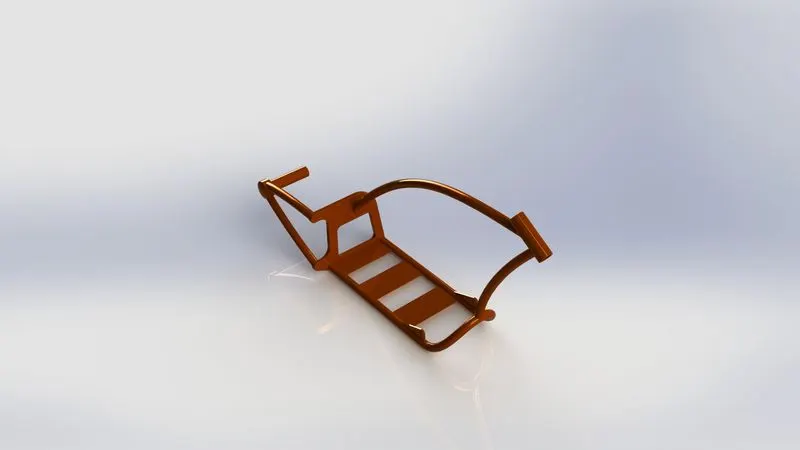
1. Chassis
Chassis is the main support structure of the vehicle which is also known as 'Frame'. It bears all the stresses on the vehicle in both static and dynamic conditions. In a vehicle, it is analogous to the skeleton in living organisms.
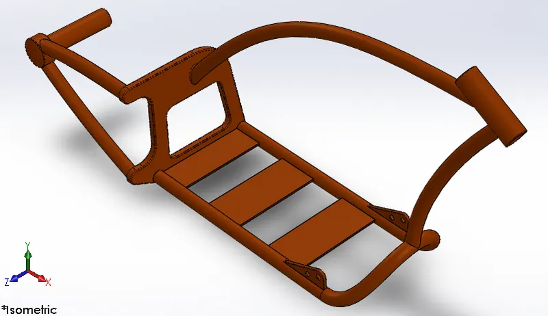
Fig 1.1 Isometric view of Chassis
Commands used in creating chassis are:
a)Sketch:
When you open a new part document, first you create a sketch. The sketch is the basis for a 3D model. You can create a sketch on any of the default planes (Front Plane, Top Plane, and Right Plane), or a created plane.
b)Projection curve:
You can project a sketched curve onto a model face to create a 3D curve. You can also create a 3D curve that represents the intersection of two extruded surfaces generated by creating sketches on two intersecting planes.
Sweep creates a base, boss, cut, or surface by moving a profile (section) along a path. A sweep can be simple or complex.
To generate the sweep swept geometry, the software creates a series of intermediate sections made by replicating a profile at various positions along the path. The intermediate sections are then blended. Additional parameters can be included in the sweep feature such as guide curves, profile orientation options, and twist to create a wide variety of shapes.
d)Split:
Use the Split feature to create multiple parts from an existing part. You can create separate part files, and form an assembly from the new parts.
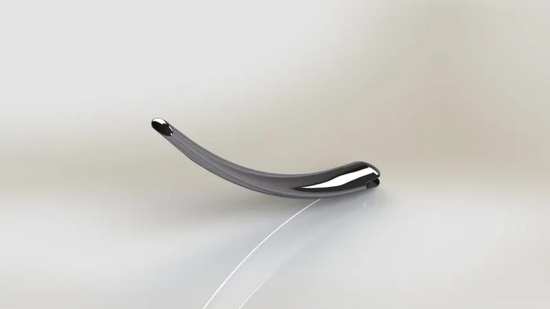
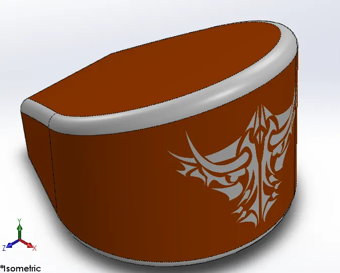
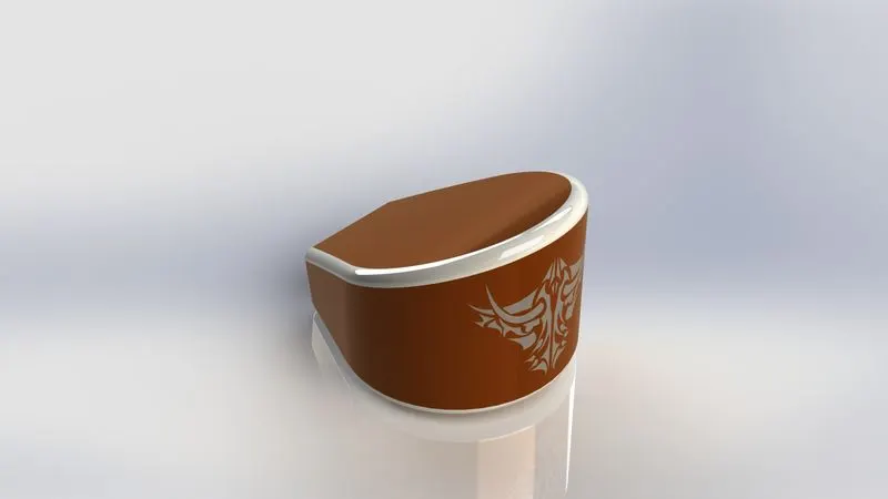
A wheel is a circular block of a hard and durable material at whose center has been bored a circular hole
through which is placed a front axle bearing about which the wheel rotates when the moment is applied by gravity or
torque to the wheel.
Wheel consists of
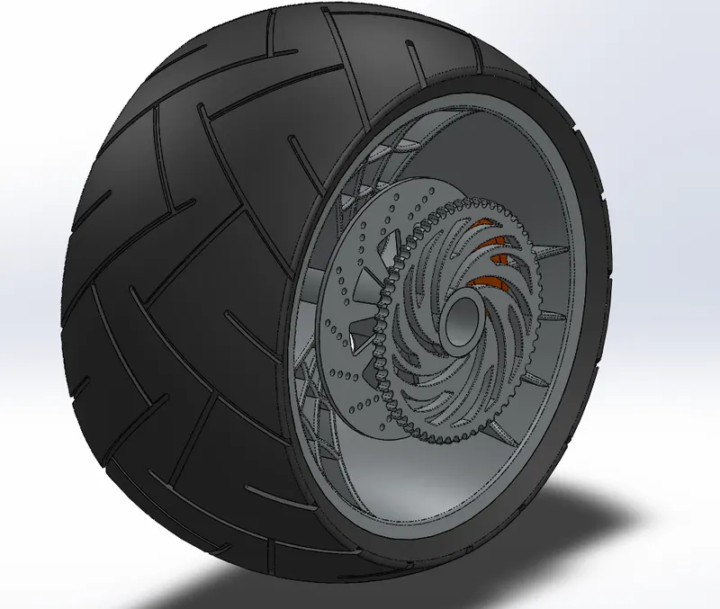
Fig 1.13 Isometric View Of Rear Wheel
• Rim
• Brake Caliper
Rim:
The rim is the "outer edge of a wheel, holding the tire. It makes up the outer circular design of the wheel on
which the inside edge of the tire is mounted on vehicles such as automobiles.
Brake Caliper:
A disc brake is a type of brake that uses the calipers to squeeze pairs of pads against a disc or 'rotor"
to create friction. This action slows the rotation of a shaft, such as a vehicle axle, either to reduce its rotational speed
or to hold it stationary.
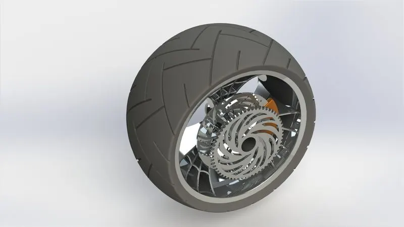
Fig 1.14 Rendered Image Of Rear Wheel
8. Front Wheel:
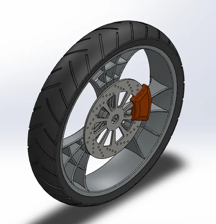
Fig 1.15 Isometric View Of Front Wheel
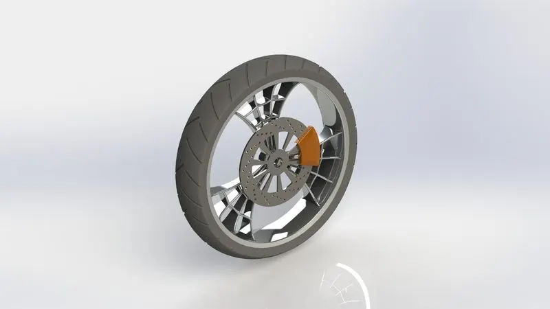
In this session, I modeled the various components of the American chopper's front wheel. After modeling the rim, rotor, brake caliper, and tire, I gave appropriate aesthetics to each component. I started by drawing a cross-section of the rim and hub. Then, using the 'Revolve Boss/Base tool,' I rotated the sketch along an axis. After sketching essential designs, a single spoke was built using the spline tool, and unwanted materials were deleted using the Extruded Cut tool. The spokes were mostly designed using the '3point arc' paradigm, which was influenced by the spider web model. The 'Circular Pattern' tool was used to generate the remaining two spokes at identical distances around the hub after completing a single spoke. The brake caliper and disc were then modeled. The holes and cuts on the rotor were modeled using both a linear and circular pattern. Finally, the tire was designed to fit the rim. The 'Convert entities' tool came in handy when sketching the tire. Then I drew a cross-section of the tire and rotated it around a makeshift axis. The next stage was to design the tread patterns on the tire. Using the '3 points center rectangle' tool, I began designing the tread pattern and provided the essential dimensions. Finally, the tread pattern was created on the tire's surface, and the tread patterns were applied uniformly using the 'Circular Pattern' tool. Finally, appropriate appearances were applied.