Week 9 - Project - Master Section Development
Aim- Is to design B-Pillar lower using Master section.
Objectives:-
Create closed body of the Given B pillar Lower.
Crete tooling axis and follow design rules.
Follow the Master section to create flange.
Follow the master section for thickness and to create the Closed volume.
Follow master section to create Attachment features.
DESCRIPTION:
MASTER SECTION:
Master Sections are the guides for design requirements which shapes the component after technical styling of Class A Surfaces The
body frame is mainly composed of floor longitudinal beams, upper side beams, door side beams, and front cover, the rear beam, A-
pillar, B-pillar, C-pillar, and other load-bearing beam structures are composed.
Master Sections are parameterized model of the vehicle body that outlines the guide for NPD Team.
In this Report B Pillar Cover Creation with detailed procedures of Surface Development and Attachment features are covered.
OVERVIEW DESIGN LIFE CYCLE AUTOMOTIVE INDUSTRY:
The Stages of Design Life Cycle are:
Concept Sketches: Concept sketches are rough idea of free hand sketch obtained through styling team and will be used to
prepare the Model. It is usually done through pen and paper and through the painting software. This will be used to generate the
concept for preparing the model by incorporating various styles and information obtained through the stakeholders.
CLASS A Creation: -After finalizing the concept the sketches are usually worked in software’s such as Autodesk Alias to create
Class A Surface.
Clay Modelling: -The Class A Surface is concurrently worked by clay modelers to brainstorm and benchmark the styling of the
product and later the Concept is validated by bringing up a rough clay model and then it is passed on to the Design team for
the preparation of New Product Design (NPD) CAD.
PROCEDURE:
The procedure followed in creation of the plastic New Product Design are
Tooling Axis
B Surface Creation
C Surface Creation
Closed Body Creation
B Side feature Creation
Side core Axis creation
Draft Analysis
The given Class A input is analysed to envision the part to manufacture and Tooling axis or Tooling Direction or Die line is the direction
that moulds pull apart in injection moulding. There are two mould pieces names core and cavity.
Thus, tooling direction determines Mould separation and also becomes vital in developing the plastic product which is drafted to
desired nominal angle for feasible clearance and ejection of final part from the mould.
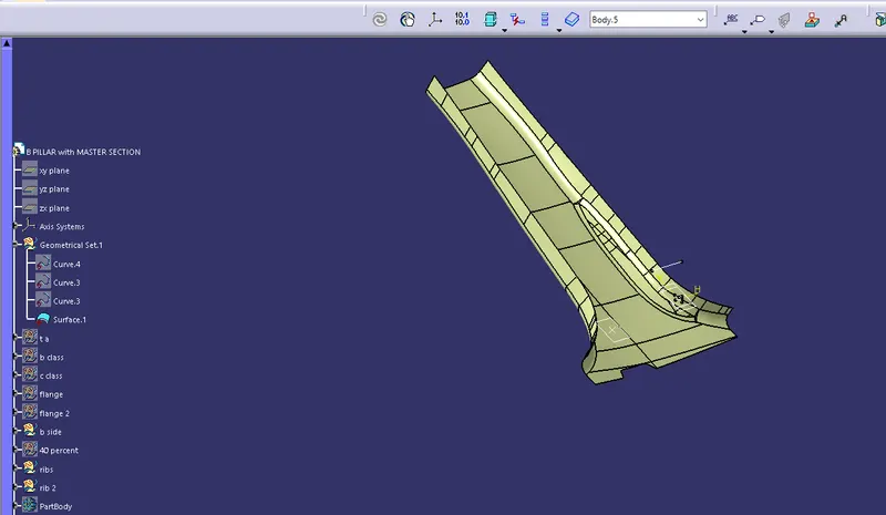
given class a
CREATION OF TOOLING AXIS:
The Steps Followed in creating Tooling Axis:
A Reference Point is created along the Surface zero and new Axis system is created.
The X Direction and Y direction along the Class A were used to create Tooling direction.
Finally, the Tooling axis is created by bisecting the two lines which provide the Master section, and it is published. Class A Surface
as input using surface operation commands Class B is developed.
The tooling Axis determines the direction of Class C boundary swept with draft direction and Draft provide in tooling axis
direction.
When viewing from tooling direction normal all the parts that are drafted should be visible, so it gives a rough idea to determine
product manufacturing in Injection moulding.
In B Pillar Model there are Two Tooling Directions one on Main tooling and other on Lifter Side that is used to eject the parts during
injection moulding.
Lifter Axis is used because the Attachment feature is bounded by close walls.
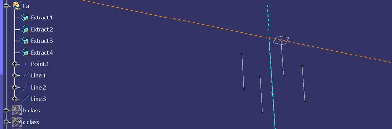
Extract the sides of the Master Section.
Extract the sides of the other Master Section Also.
Then create a bisector for these Extracts.
Then the bisection of these bisectors is the Actual tooling axis created.
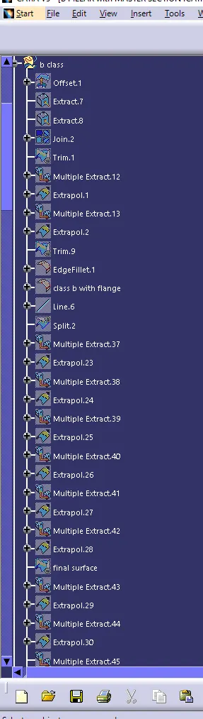
CREATION OF CLASS B SURFACE:
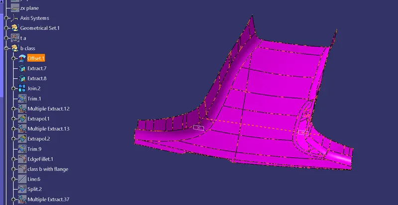
To create the Class B Surface, select the Class A surface and offset the surface to 2 mm.
After offsetting the surface, we can observe that the CLASS B surface is having a patch / missing surface. This surface needs to be
fixed by manually creating a surface.
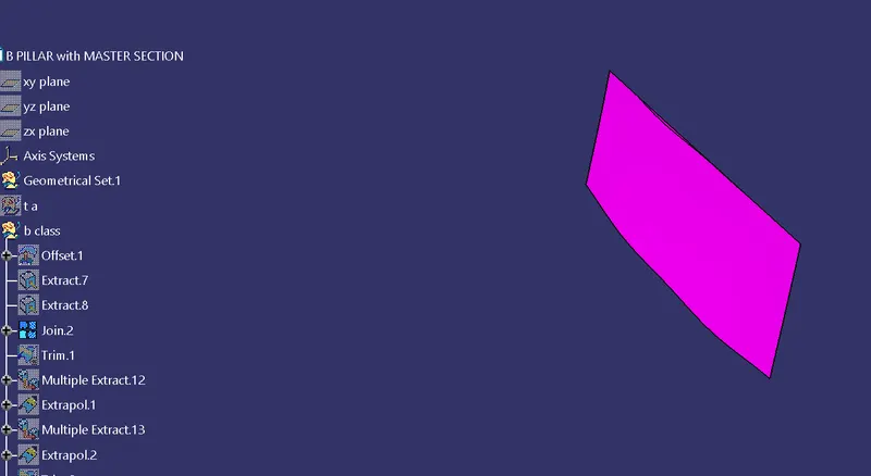
To create a surface over the patch, we first need to extract the boundaries of that edges separately and using the “multi section”
option a new surface can be created. Now join this patch surface with the offset surface to form a CLASS B surface.
So, to clear this use multi section surface option to close the gaps formed.
The gaps formed is closed and the Class B Surface Formed is Ok.
CREATION OF FLANGE:
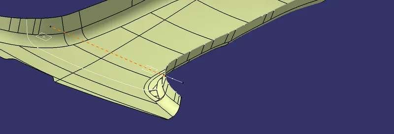
From the master section it can be observed that the B Pillar is having Flange but the CLASS A surface which was given to us as input
do not have any Flange.
So, to create a Flange on both A & B surfaces we first need to extract the boundaries of the CLASS A / B surface as shown in figure
below.
After extracting the boundaries apply a smooth option to it to avoid any surface continuity issues
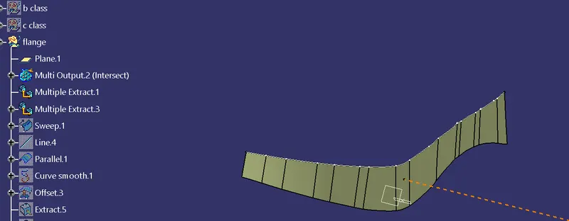
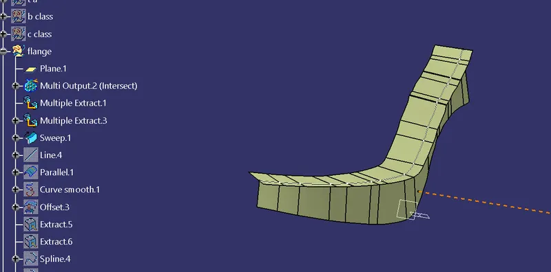
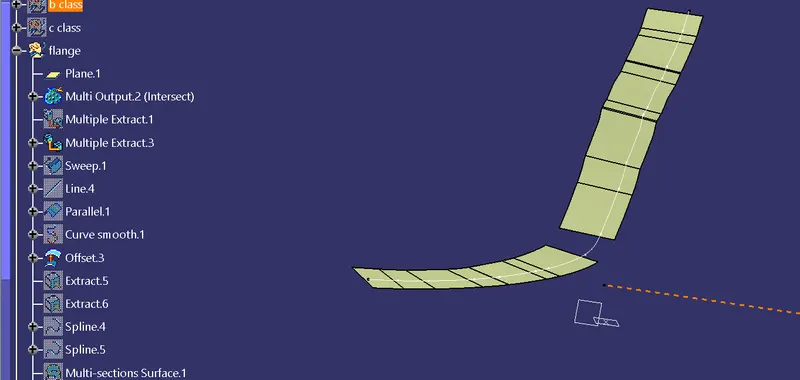
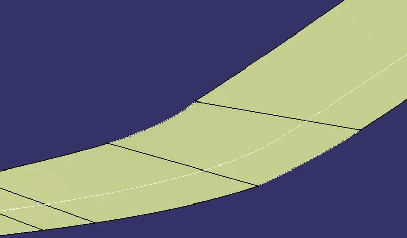
Surfaces of CLASS A / B which are attached to the boundary need to be extracted first which will act as a reference surface for the
Flange while sweeping.
Now sweep the boundary with the reference surface (surfaces which we extracted) and give an appropriate angle such that the
Flange is aligned with the master section.
Offset the Swept Surface to 2mm.
Similarly, Do it on the other side of the B Pillar
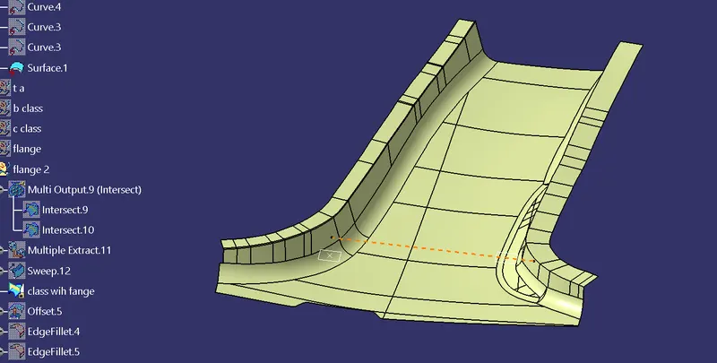
Now Join the Sweep surface with the Class A surface and the Offset surface with the Class B Surface to get surfaces attached with a
Flange.
and now provide the fillets by measuring in class a.
CLASS C SURFACE CREATION:
To create a CLASS C surface, first extract the boundaries (all edges separately) of the CLASS A surface (the surface with FLANGE) as
shown in below figure.
After extracting the boundary, we need to perform smooth (max. Deviation as 0.001mm) operation on it to create a continuous
tangent surface.
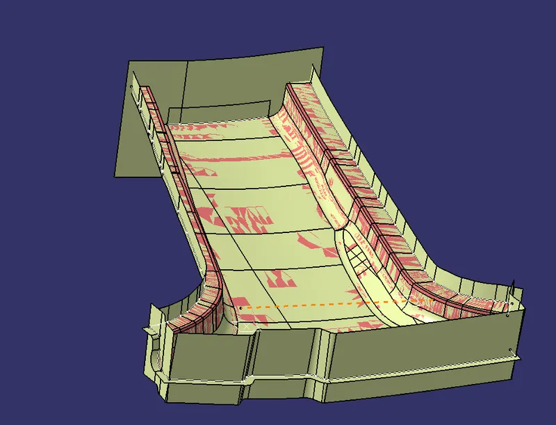
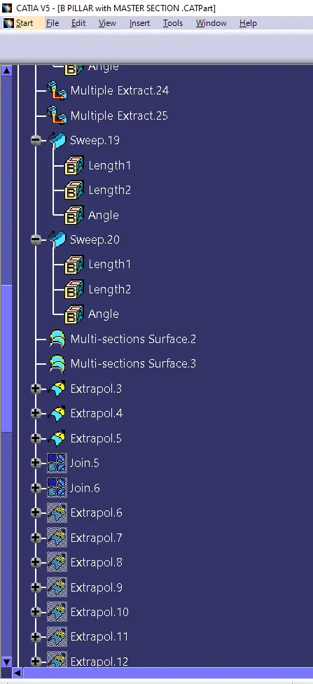
trim the sweep after extraploing them.
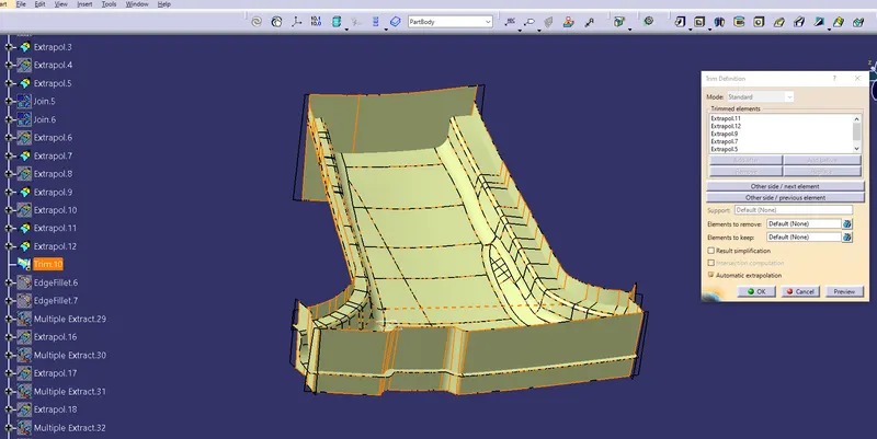
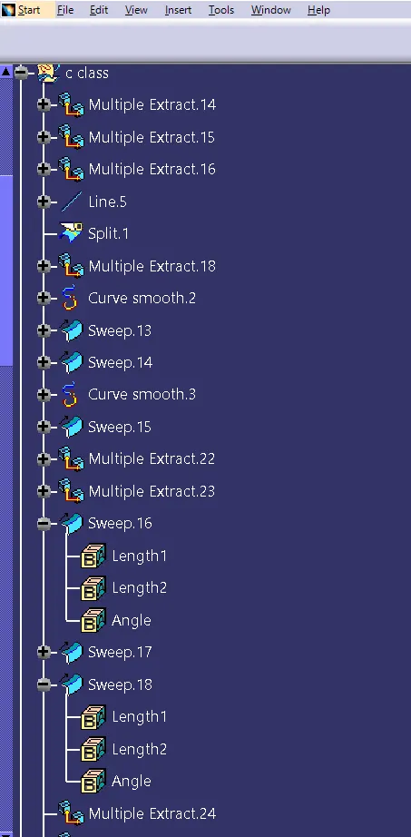
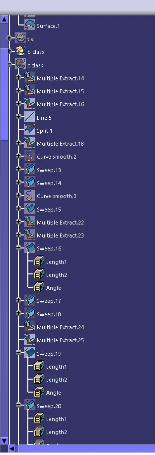
Now using the ‘sweep’ option create the surface. To perform this operation, go to the Toolbar > Sweep > Profile type > Line > Subtype >
With draft direction > Guide curve 1 - (select the extracted boundaries) > Draft direction - (select the tooling axis) > angle as 3 deg
and give any suitable length and press ok.
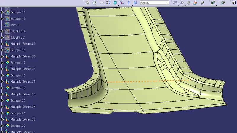
extrapolate class b and class a with flange in order to get trimmed with the sweeps. and to have a closed surface.
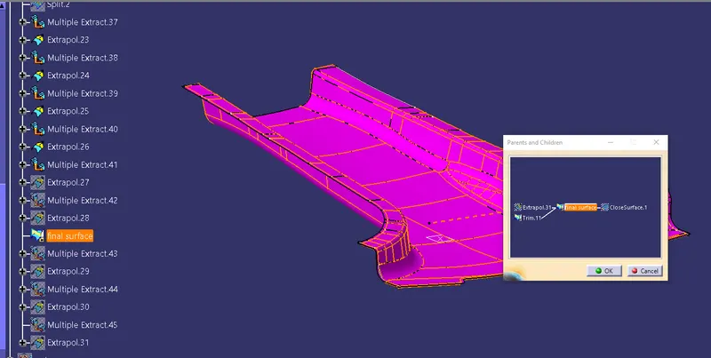
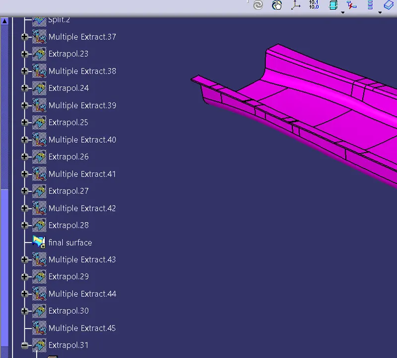
Note: The boundaries of the CLASS A surface need to be extracted separately and the sweep operation also needs to be performed
separately. It is not possible to create a C surface with a single sweep following the Draft Direction.
Once these sweep surfaces are created, trim them to join the surfaces.
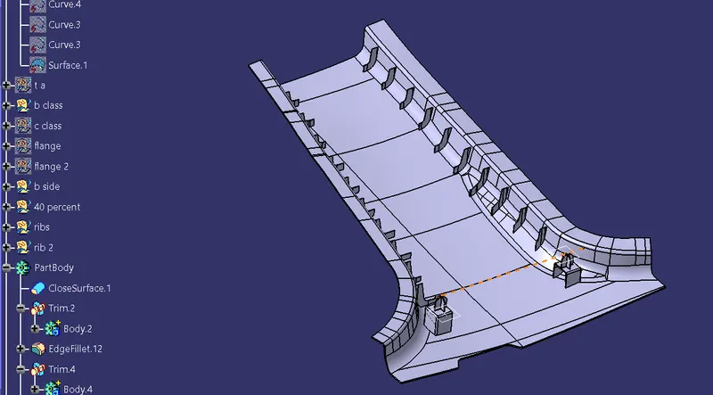
FINAL TRIM:
To create the B Pillar component, we need to join all these surfaces (i.e., CLASS A, B and C surfaces).
First join the CLASS A surface with the CLASS C surface and then trim this joined surface with the CLASS B surface to get the final
output.
ENGINEERING FEATURES:
DOGHOUSE:
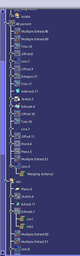
Doghouse is an engineering feature that is used in plastic trim design. It is used as a supporting feature for other engineering features
like snaps, locators etc. that are mounted on the Doghouse to increase their strength and to avoid the sink marks.
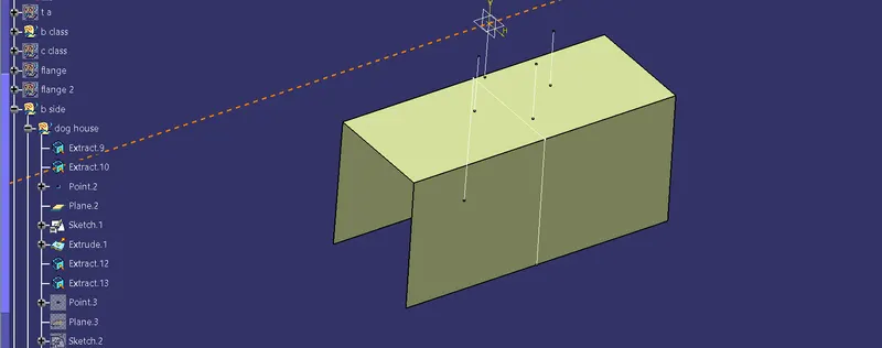
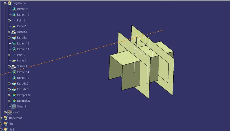
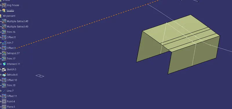
To create a Doghouse, we need to follow the master sections which were given to us as an input. The top surface and the supported
walls of the Doghouse on which the locator is laid is created by simply extracting the lines from the master section in a sketch and
extruding it to a certain length as shown in figure below.
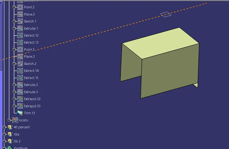
thichne the surface by 2 mm since the given master section is 2 mm
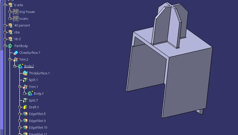
now sketch the loacators based on the given master section
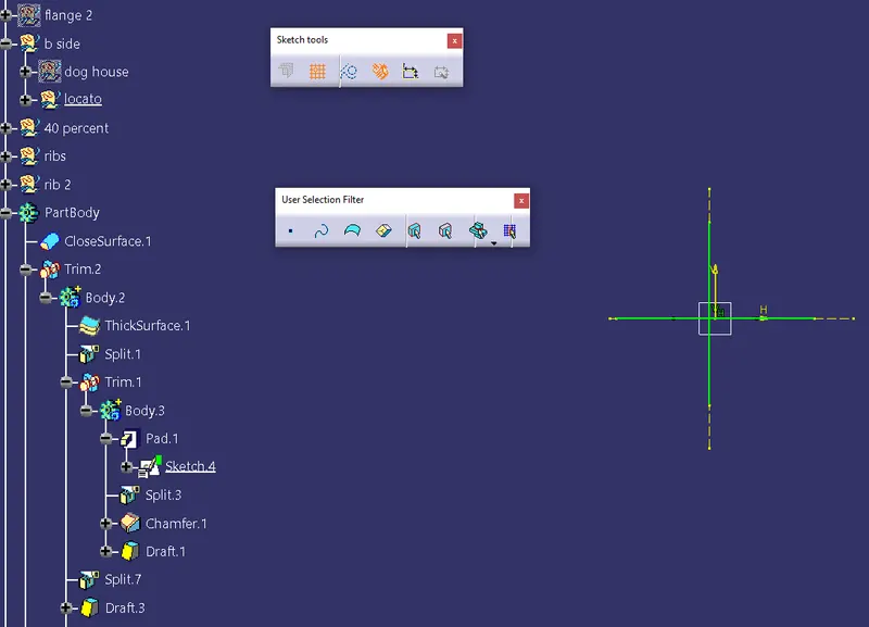
Locators are a great way to make sure the parts we are putting together fit the way we want them to fit. To create a 4-way locator, we
need to create a sketch with two lines intersecting each other perpendicularly forming a ‘+’. Once the sketch is created, pad it to form
a locator.
Note: The 4 - way locator is created on the top surface of the Doghouse following the master section.
A draft of 0.5 deg is given to the locator and a chamfer of 5 mm at 45 angles is given to the top edges of the locators.
The inner walls of the Doghouse are created at an offset value of 1.2mm from the outer walls and the top surface for the inner walls is
created by intersecting the CLASS A surface with the back wall of the Doghouse.
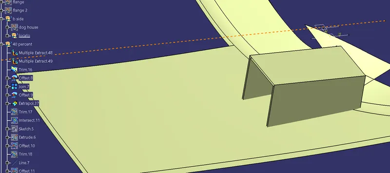
This surface is then split with the close solid to create the inner walls of the Doghouse.
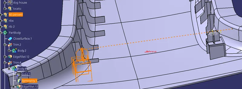
now translate the dog house by taking the midplane between the master section reference by plotting plane using parallel through plane.
RIBS:
Ribs are created to increase the strength of a part without increasing the thickness of its walls. Because less material is required, ribs
can be a much more cost-effective solution as well.
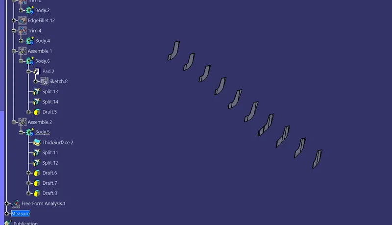
To create a rib, we first need to draw a straight line (where we want a rib) in the sketcher workbench. After creating the line, extrude it
and pad it.
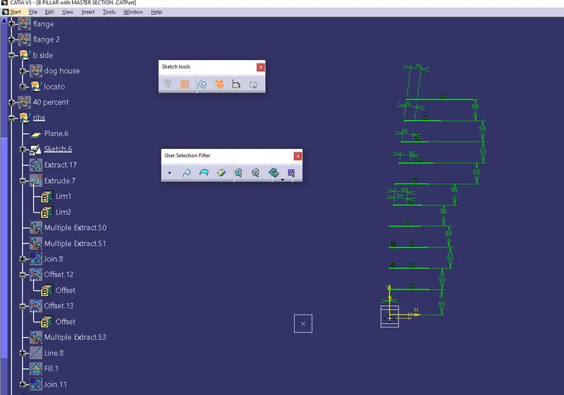
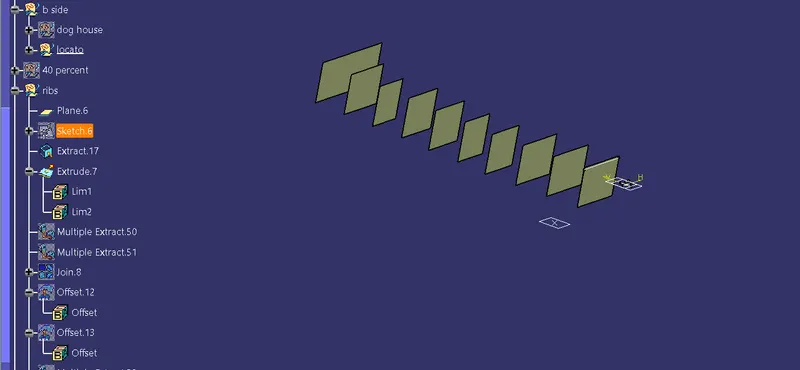
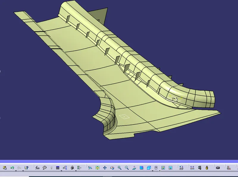
Since we need to create multiple ribs which are 50 mm apart, first go to the CLASS A / B surface and extract the boundary/edge
where the flange is connecting to the main body. Now using these boundaries, create repetition points which are at 50mm from each
other.
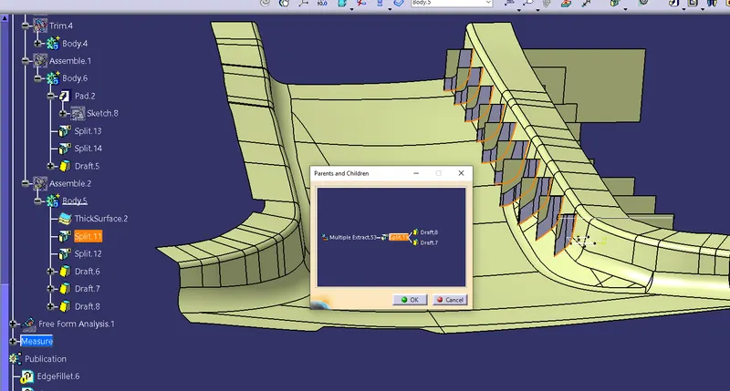
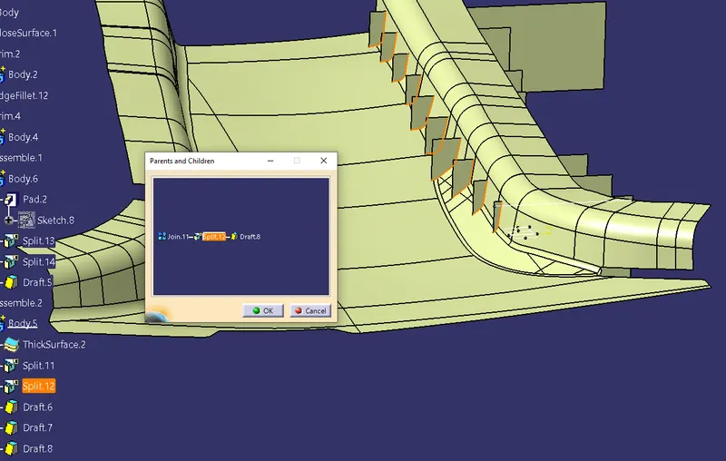
Now copy the rib (solid body) which we created and paste it in the main tree structure. Using the translate option the copied rib can
be moved from one point to another. Repeat the above step for creating all the ribs and position it on the points that we have created
using the repetition points option.
Offset the CLASS B surface to 10 mm and trim the ribs with it removing the excess portion of the ribs and give a draft of 0.3 to the ribs.
Create the ribs on the other side also.
Once all the engineering features are created, add it /trim it to/with the main body i.e., B Pillar and give appropriate fillet value to all
parts of the body
DRAFT ANALYSIS ON FINAL MODEL:
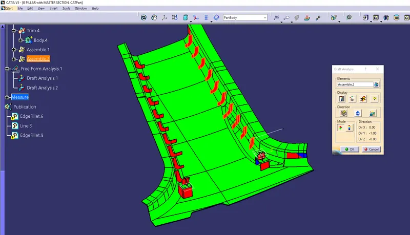
To perform Draft Analysis on the 3D CAD model, go to menu bar > select insert > Analysis > Feature Draft Analysis.
To give draft direction, use the compass and align it with the tooling axis which we created for the model. Once it is properly aligned,
select the surface of the model which will show us the draft angle given on the component. Make sure the draft angle on the
component is having 3 deg draft value (component showing green in colour).
MAIN TOOLING AXIS:
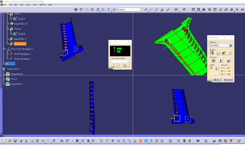
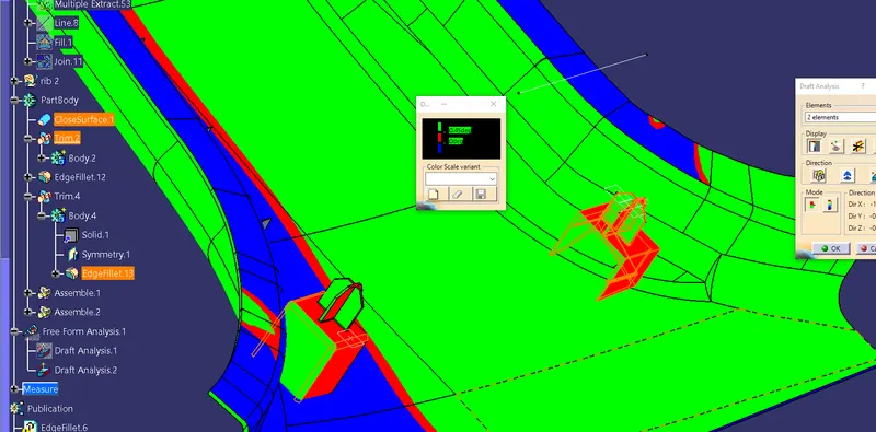
LIFTER TOOLING AXIS:
Note: Draft value ranging from 0 - 3 deg will show the component Blue in colour.
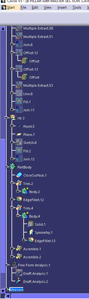
Using the Analysis option under Display Tab, we can check / analyse the exact draft value at any point on the given model.
CONCLUSION:
B Pillar component with engineering features using the master section and Class A surface as an input have been successfully
created and draft analysis have also been performed for the same.