Week 9 - Project 1 - Door Trim Lower with Engineering Features
Door Trim Lower with Engineering Features
AIM
Create the Door Trim Lower Plastic component through the given Class-A surface. Also, to create heat staking and locators considering all the design rules.
OBJECTIVE
- Create Ta cooling axis for the given CLASS -A surface.
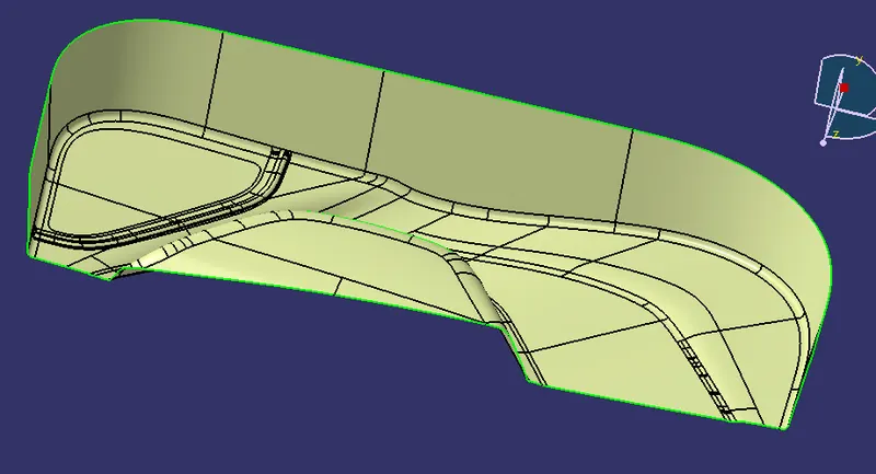
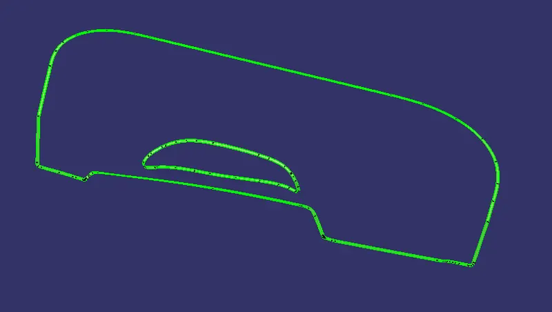
- Create the CLASS B and C surfaces of door trim using the given CLASS-A surface.
- Create a final surface model and convert it into o solid body us the ing close surface command in the part design workbench.
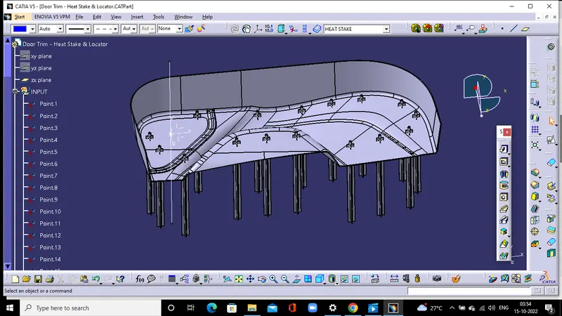
- Create Locators and Heat stakes on the B side of the door trim part body.
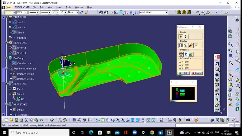
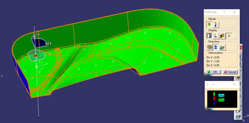
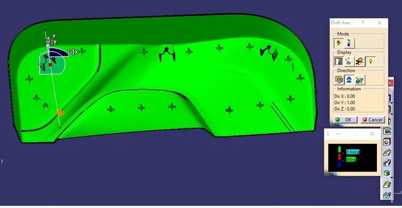
- Perform draft analysis for both Class-A surface and Final part body.
Procedure for Tooling axis creation
- Check the best possible tooling direction by manually adjusting the compass.
- By analysing it is found that the y axis as tooling direction would clear all the faces.
- Now extract any surface and create a mid-point on it.
- Since all the faces of the given surfaces have draft angle more than 3 degrees, I have chosen the normal to the surface method to create the tooling axis.
CLASS A SURFACE WITH DRAFT ANALYSIS
CLASS B SURFACE
CLASS C SURFACE
FINAL JOIN
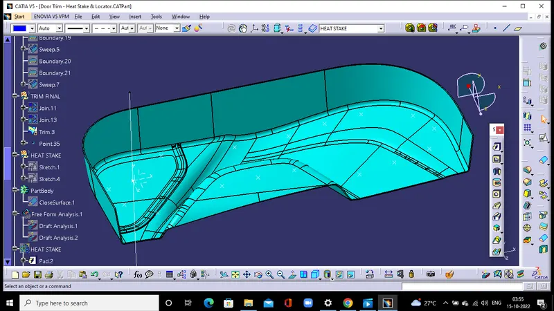
DRAFT ANALYSIS OF TRIM
HEAT STAKE CONSTRUCTION
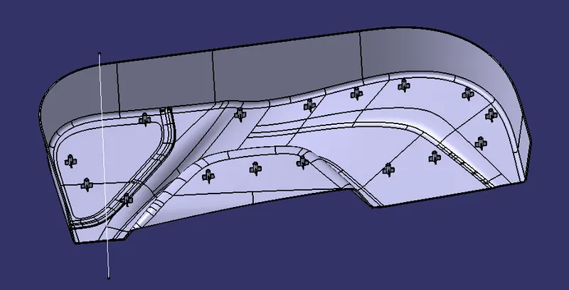
Trim it with the main body
LOCATOR
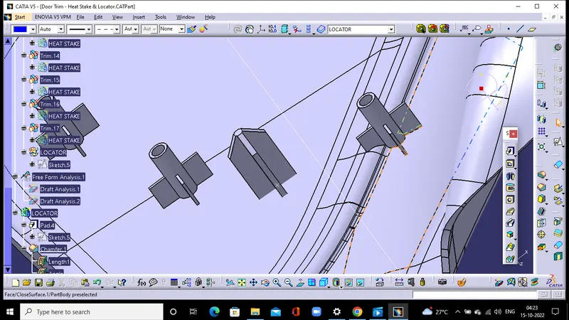
DOG HOUSE
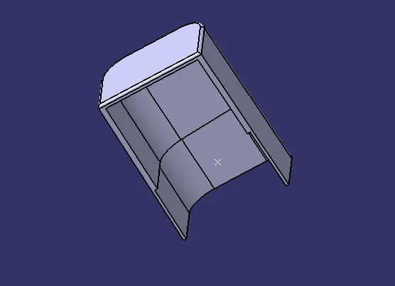
FINAL ASSEMBLY
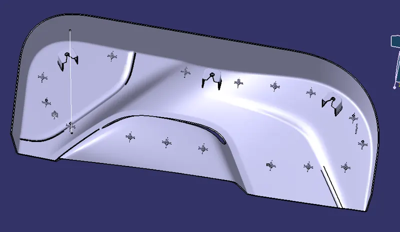
DRAFT ANALYSIS OF FINAL ASSEMBLY
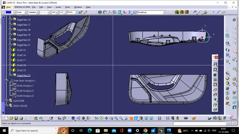
VIEWS
CONCLUSION
The door trim part has been designed with the engineering features by following proper tree structure.