Roof Design
DESIGN OF ROOF
AIM: To design a car roof for the given styling surface based on the design considerations.
Introduction:
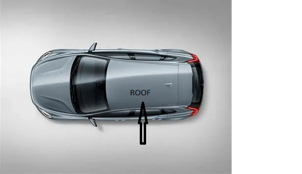
An automobile roof or car top is the portion of an automobile that sits above the passenger compartment, protecting the vehicle occupants from sun, wind, rain, and other external elements. Because the earliest automobiles were designed in an era of horse-drawn carriages, early automobile roofs used similar materials and designs.
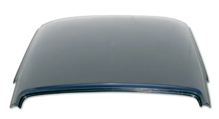
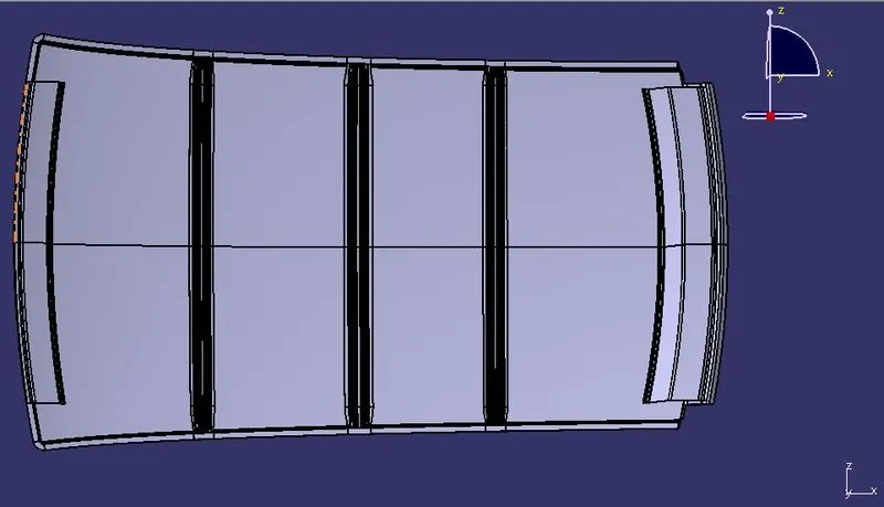
The roof has an outer panel which is the styling part. Strengthening parts are present below an outer panel of a roof, which are front roof rail, Bow roof, Centre roof rail, and Rear roof rail.
NEED OF REINFORCEMENTS :-
If the roof is flat it is very weak and cannot able to with stand the forces like snow , so in order to increase the strength of the roof these reinforcements like front roof rail, central roof rail, rear roof rail and the bow roofs are introduced and joined to the flat surface of the roof with the different joining process
Different types of reinforcements are as follow :
1)Front roof rail
2)Bow roofs
3)Centre roof rail and
4)Rear roof rail
DESIGN CONSIDERATIONS FOR A ROOF :
The below mentioned ponits are the the considerations to be done on designing the roof:
- Visibility criteria
- Head clearance
- Curvature study
- Heat distortion and snow load criteria
- Draft analysis
OUTER ROOF PART
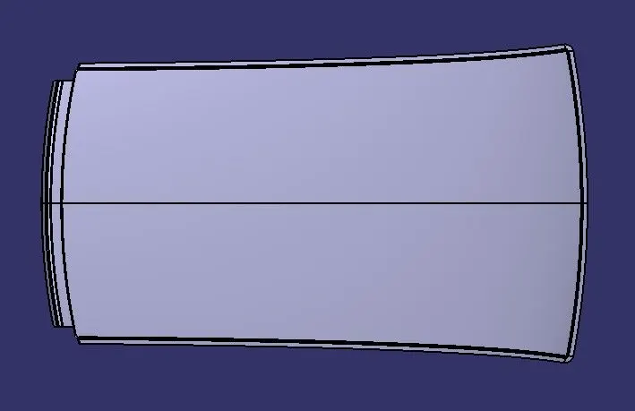
From the given styling surface the outer surface is extracted and some modifications are made by providing ditch area and clearance at the rear for the back door to open and close.
FRONT ROOF RAIL :
Front roof rail is the one which joins the wind shield glass , body side outer and the inner panel also. Here the front roof rail is designed based up on the master saection given.
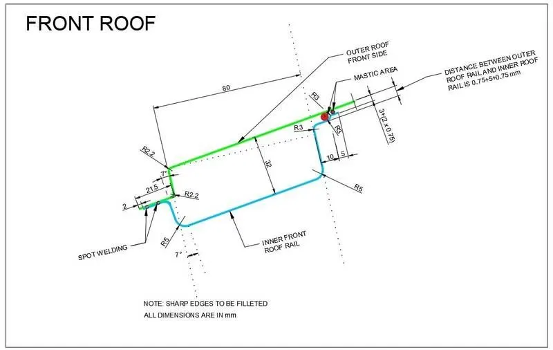
By considering the above master section the front rail is designed by offsetting the given class A surafce.
The are given zero spacing at spot welding places and gaps a are provided at the mastic points.
The design will be as follows.
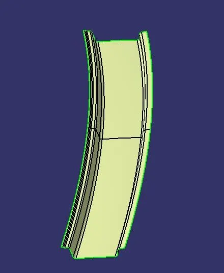
REAR ROOF RAIL :
Rear roof rail is the one which joins the back door and the body side outer.
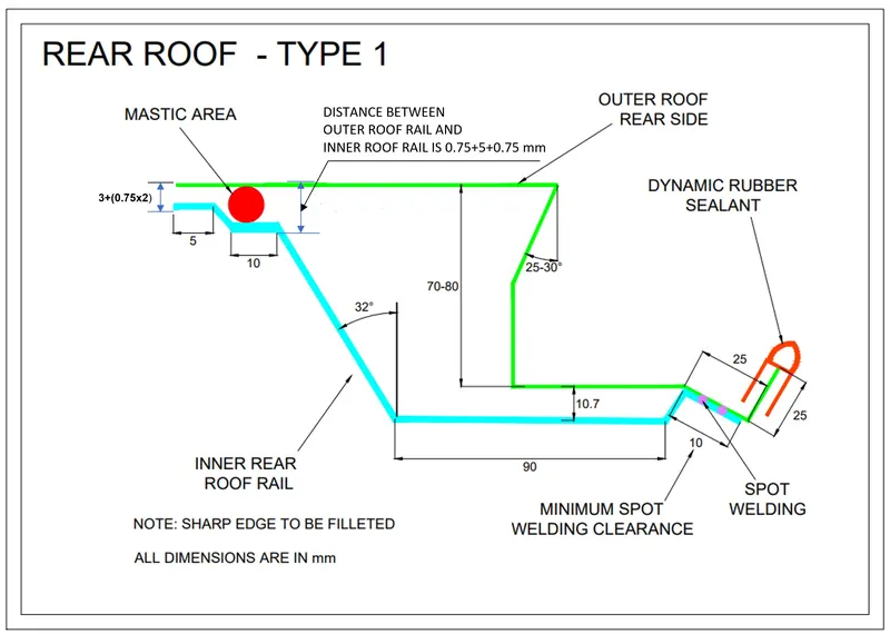
By following the master section the rear roof rail is designed and some clearance is provided for the opening and closing of the back door.
At the rear roof rail there will be negative draft which will be done by bending process.
The rear roof rail design will be as follows.
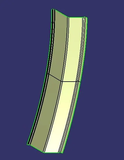
CENTRAL ROOF RAIL : -
Center roof rail is used as a cross member between Left hand and right-hand bodysides. this supports the roof a lot.
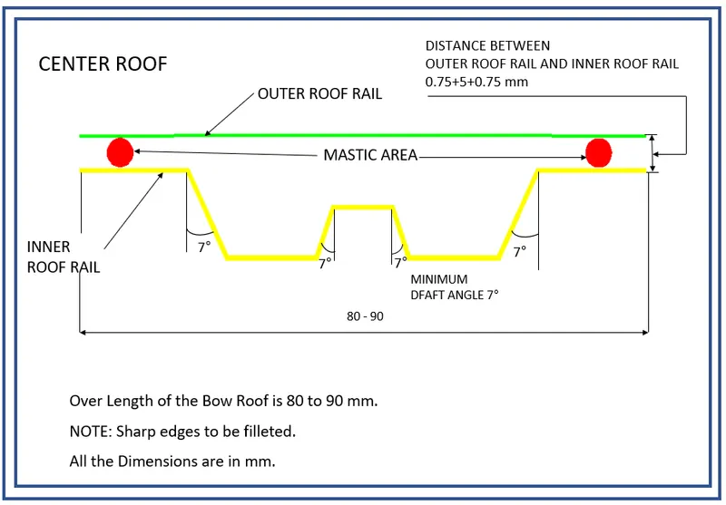
By following the master the design is made by providing 7 degree draft angle.
The design will be as follows.
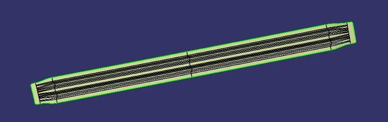
BOW ROOFS :-
The bow roofs are give to improve the torsional stiffness and load bearing capacity of the roof structure . The number of bow roof present is depends on the overall size of the roof.
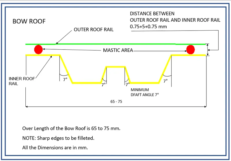
The bow roof are same as the centre roof except they have less cross section area and are present at left and right of the centre roof along the car X axis.
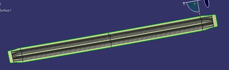
Bow Roof Prediction- This calculation provide a guidline to decide position and number of bow roofs in a vehicle.
Bow–Roof Prediction Formula
W = [1.73 x 10^(-3) x L] + [1.85 x 10^(-8) x (R^2)/t] + [ 1.10x10^(-3) x l] - 2.68
Where,
L = Roof Length in X-Direction[mm](Roof dimension in 0-Y)
R = Roof curvature
R = 2(Rx*Ry)/(Rx+Ry)
Rx = X curvature
Ry = Y curvature
t = Roof plate thickness [mm]
l = Bow Roof Span [mm]
If the W is < 2.7 then the design is ok if not we have to reposition the bow roofs or to increase the number of bow roofs.
The above parameters are taken from the design.
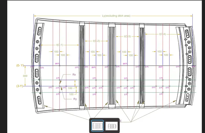
By doing the calculation as per the drawing the W we got in the cases are
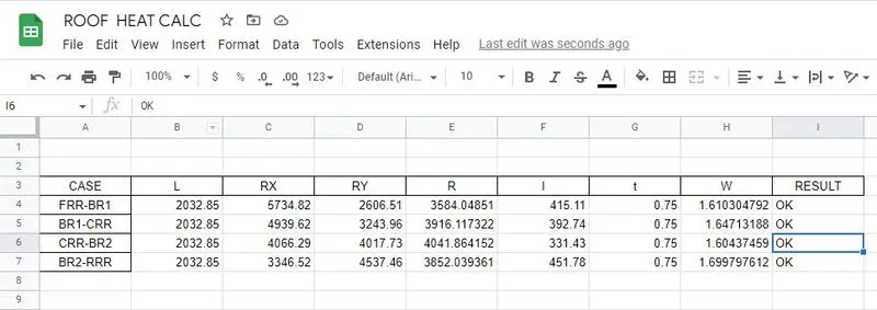
Hence the above claculation gives positive signal for our design.
SNOW LOAD CRITERIA :-
- This test is done to know how is the roof behaving when there is a snow over.
- Normally due to the snow weight the dent will happen.
- But the roof should be designed in such a way that when the snow is remove from the roof then it should be in its original position.
- This is the basic requirements for snow load criteria
Snow Load Prediction Formula
Qr = [Iy x t2] / [α x s x [(Rx + Ry)/2]2 x 10-8]
Note: The Qr value given over here is correct. There was a typo error in the formula given in the video.
Where,
α = My x Lx2 x 10-12 , My = Y(Ly-Y)
t = Roof plate thickness [mm]
Ly = Distance between the front and rear roof Rails on the Vehicle along with 0Y[mm]
Length of Roof panel with the center point between Roof rail Front /Rear as the front and rear reference point.
Lx = Distance between the Left and Right end of the roof on the Roof BOW [mm]
The width of the roof panel is exposed on the surface.
Y = Distance front Front Roof Rail to Roof BOW[mm]
s = Distance for which Roof BOW bears divided load [mm]
s = L1/2 + L2/2
Iy = Geometrical moment of inertia of Roof BOW (Y cross-section )[mm4]
Rx = Lateral direction curvature radius of roof panel Y cross-section on Roof BOW [mm]
Roof panel curvature Radius of the Length Lx in Front view
Ry = Longitudinal Direction curvature radius of the Roof panel X cross-section on Roof BOW [mm]
Roof panel X curvature radius of length s in Side view
The calculation result should satisfy the below condition
Qr ≥ 3.1
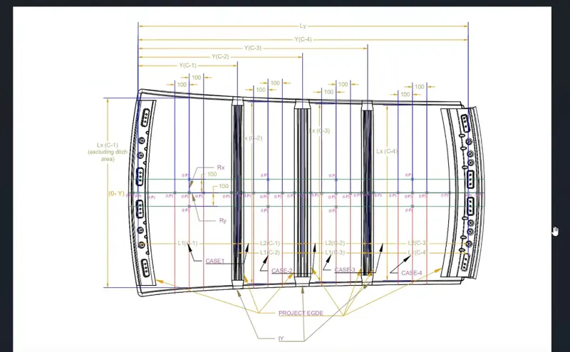
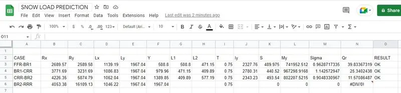
The above calculation has proved the three cases are ok with condition.
The above results implies that the design is made as per the design considerations.
MANUFACTURING PROCESS OF FENDER
- Process planning: The purpose of process planning of automotive panels is to identify the number of operations, the tasks in each operation, and the content of each task. This research proposes an automatic reasoning procedure based on expert experience and the laws of physics.
- Bending task: Bending is a process by which metal can be deformed when applying force to the subject, which causes it to bend at an angle and form the anticipated shape, which often results in it being in a ‘V’ or a ‘U’ shape.
- Trimming task: The trimming task is separated into two parts.
- Restriking task: The restriking task is necessary when surfaces deform because of springback after drawing and trimming, or the accuracy requirement is high because a surface overlaps another surface of another panel during assembly. To overcome the springback of sheet metal restriking is required.
- Piercing task: Each hole feature requires a piercing task. Hole features can be classified as basic holes, lock holes, and enlarge holes based on their different functions during assembly. A basic hole is for locating the panel, and a lock hole is for locking panels.
- Burying task: Removing the sharp edges and harmful burs from the component.
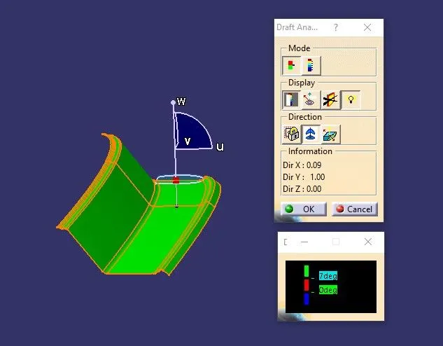
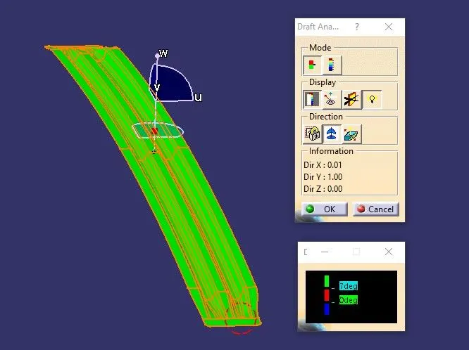
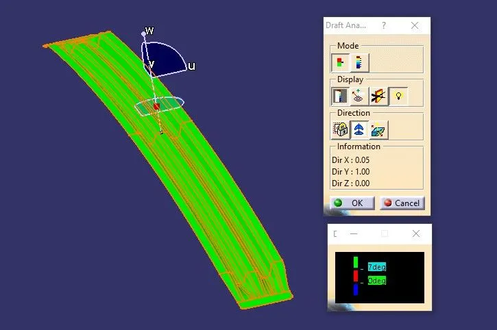
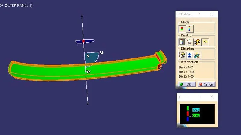
DRAFT ANALYSIS OF EACH PARTS;
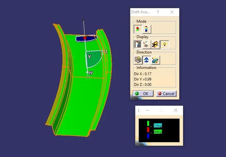
The draft anagle should be 7 and above as per sheet metal manufacturing conditions.
FRONT ROOF RAIL DRAFT
REAR ROOF RAIL DRAFT
CENTRE ROOF RAIL DRAFT
BOW ROOF RAIL
OUTER PART:
ASSEMBLED ROOF
CONCLUSION
Hence, a roof assembly was created by developing the essential flanges for the outer roof and created reinforcements for the given roof styling,curvature study on roof assembly and calculation for the position of the bow roofs has been done and also carried out draft analysis to check feasibility of manufacturing.