Fender Design
AIM: To design a Fender mounting on the given model by using Master sketch by considering the safety and manufacturing feasibility for possible mounting region.
FENDER
Fender is the American English term for the part of an automobile, motorcycle, or other vehicle body that frames a wheel well (the fender underside).
The fender is the car body part that frames the wheel. Its purpose is to prevent sand, dirt, rocks, and other road spray from being thrown into the air by the rotating tire and close the engine component.
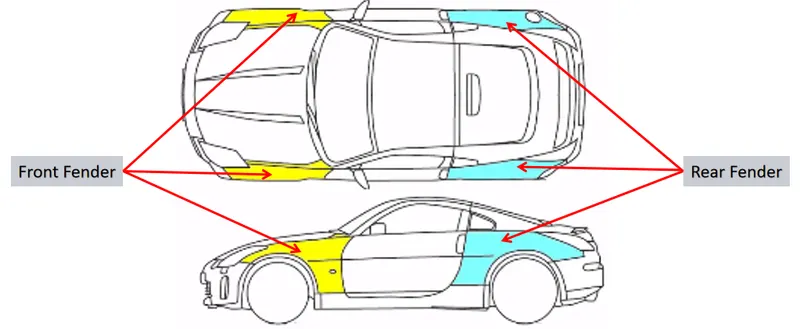
When a vehicle is moving, tires pick up stones and others and hurl them in all directions. Fenders are basically present to prevent any injuries to pedestrians and contain the motion of these particles. A pair of front and rear fenders can be found on each side of a vehicle.
Need of Fender:
- It is designed to provide resistance against wind, muds, and roadside particals.
- It is the sheet of metal covering of the car.
- Fender has a plastic part called Baffle or fender Liner which fits underside the fender to protect the metal from corrosion by stopping the flow of mud and water inside from different road conditions.
There are 2 types of fenders.
- Full Bumper Type
- Half Bumper Type
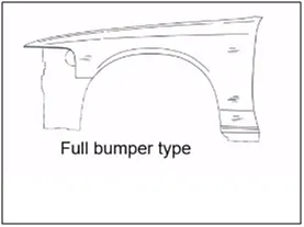
Full Bumper Type: Full Bumper Type is not used now a days because it requires large size of balnk to produce the part and it occupies more space.
Half Bumper Type: Half Bumper Type Half bumper is used because the waste of material is less & can produce two fender at the same time by slightly increase the raw sheet. and to reduce the weight & cost mostly bumper fender are been produced.
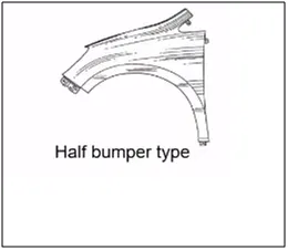
We are changed from full bumper type to half bumper type to reduce the scrap rate per blank. In the full bumper, we can only produce one Fender per blank, whereas as a half bumper type we can produce 2 fenders per blank.
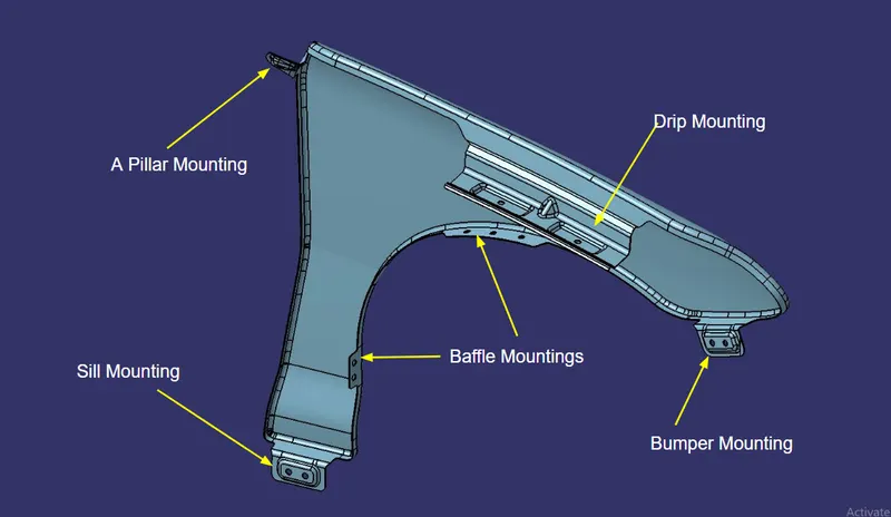
There are generally 5 mountings on a Front fender-
1. Body
2. A-Pillar
3. Sill
4. Cowl
5. Drip
GIVEN MASTER SECTION
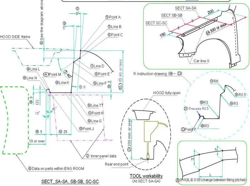
DRIP AREA MOUNTING
The master section is given for the drip area mounting.
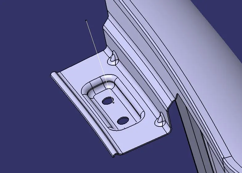
- The drip area would be recognizable fom the opening between Hood and Fender.
- This mounting is attached to the engine compartment of the car.
- A min 150mm distance is kept from the front side and a distance 300mm or less can be kept on the rear side .
- This is to avoid the springback during the manufacturing . the edge of the mounting should atleast 10mm away from any nearby component in the engine.
- The drip area should be less than 40mm.
- The embosess that are created on the drip mounting should be flat with respect to the curvature.
- The beads are provided at the edge of the drip mounting to increase the stiffness
SILL MOUNTING
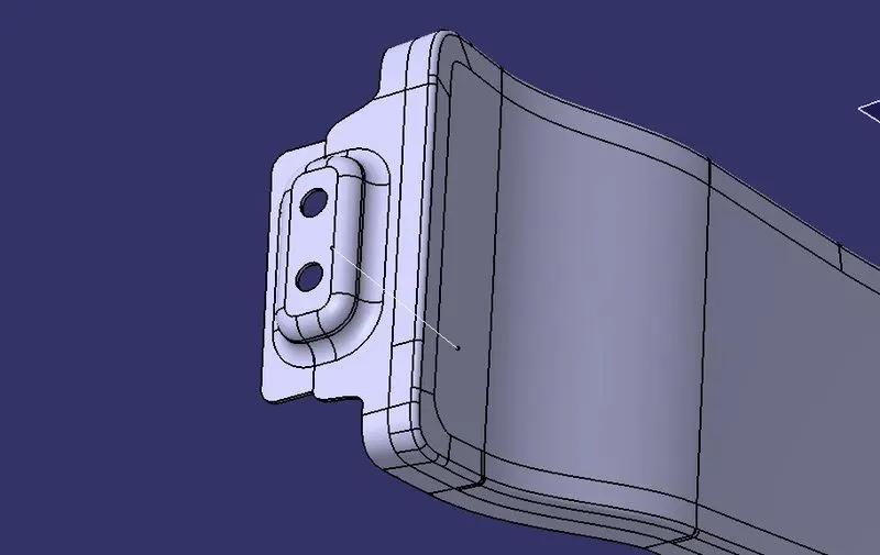
- This is palced basically at the botom of the fender. The mounting part is created such that it firmly fits to the sill.
- The embosess that are created on the drip mounting should be flat with respect to the curvature.
A-PILLAR MOUNTING
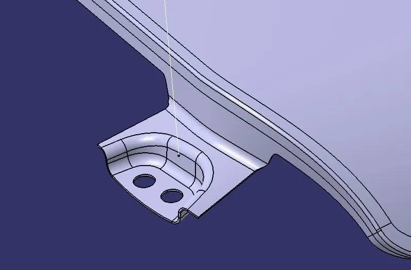
- A-pillar mounting is a vertical support on a vehicle. It holds the windshield set up and just downside to the A-pillar fender is mounted to hold the position.
BUMPER AREA MOUNTING
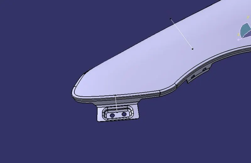
- It is placed at the front side of the fender,the bumper mount area of fender, mounts on the chassis to hold the position.
- Since Bumpers are mounted over the fender it is called Bumper Mounting Area.
BAFFLE AREA MOUNTING
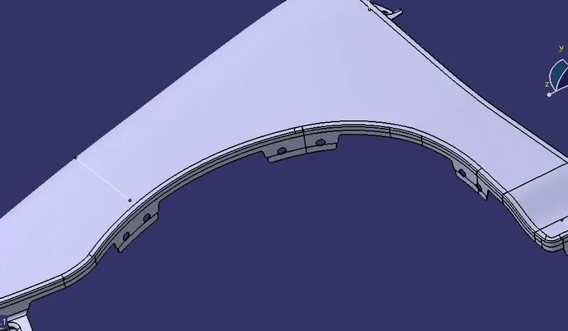
- Usually a baffle is mounted on the fender of the car . It is mounted on the wheel arch area .
- A plastic unit is placed which is called baffle/splash fender linear mounting is placed.
- These mountings are created for fixing the baffle/splash mounting.
MANUFACTURING PROCESS OF FENDER
- Process planning: The purpose of process planning of automotive panels is to identify the number of operations, the tasks in each operation, and the content of each task. This research proposes an automatic reasoning procedure based on expert experience and the laws of physics.
- Blank size calculation.
- Trimming task: The trimming task is separated into two parts.
- Restriking task: The restriking task is necessary when surfaces deform because of springback after drawing and trimming, or the accuracy requirement is high because a surface overlaps another surface of another panel during assembly. To overcome the springback of sheet metal restriking is required.
- Piercing task: Each hole feature requires a piercing task. Hole features can be classified as basic holes, lock holes, and enlarge holes based on their different functions during assembly. A basic hole is for locating the panel, and a lock hole is for locking panels.
- Burying task: Removing the sharp edges and harmful burs from the component
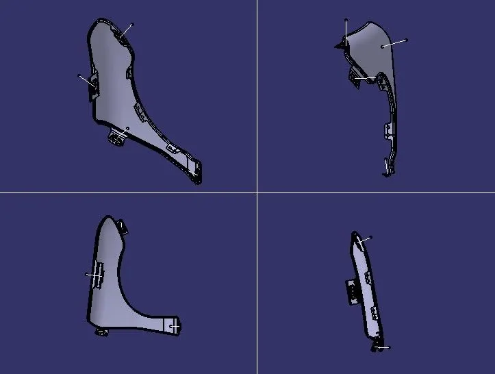
MODEL IMAGES
FRONT VIEW
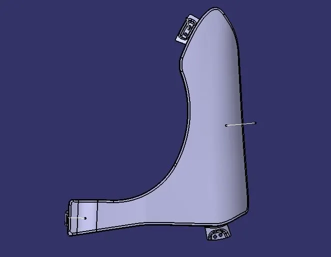
SIDE VIEW
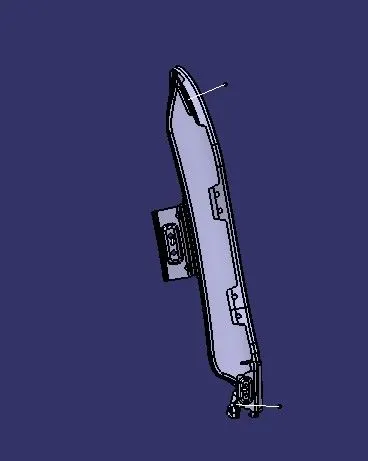
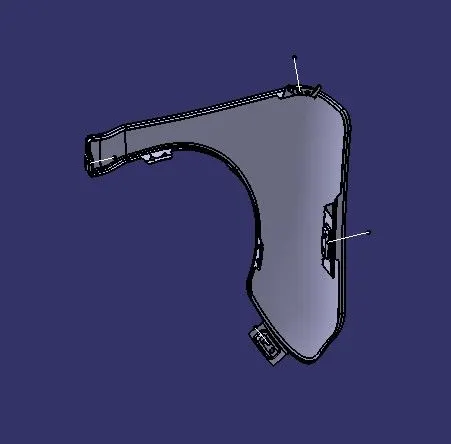
DIFFRENT VIEWS
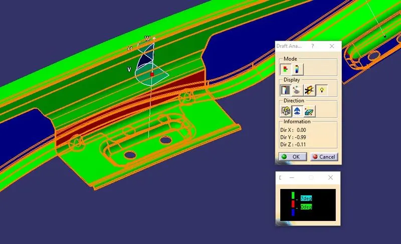
DRAFT ANALYSIS
CONCLUSION
The fender design has been done for the given styling surafce and master section on considering the designing parameters.