Week 8 - Challenge 2 - Switch Bezel Design
AIM
To design a switch bezel using the Class A design provided. And to perform draft analysis on both the class A and the final product.
INPUT
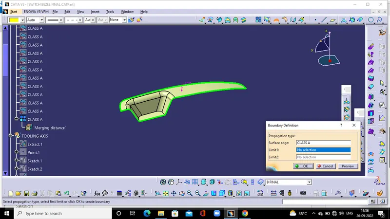
Apply boundary on the given class A to check wheather it is suitable for design
CREATION OF TOOLING AXIS
The tooling axis is the direction in which the core and cavity opens and ease the operation of ejection of the finished part from mould. The tooling axis is important for removing the material when finished.
Bisecting the class A inclined suraface in the sketcher workbench create a dummy toolind axis for the opposite faces.
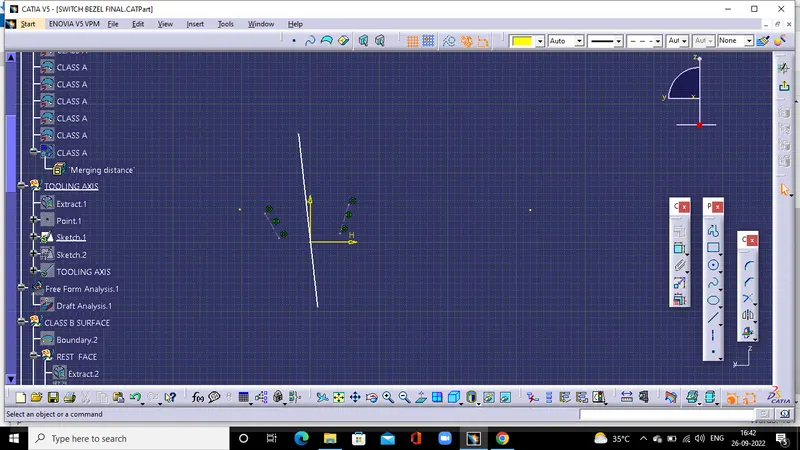
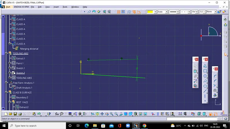
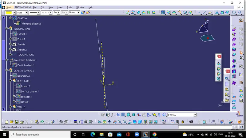
For other adjacent face provide the nominal draft line of angle 3deg. and by bisecting this two dummy tooling axis create the main tooling axis.
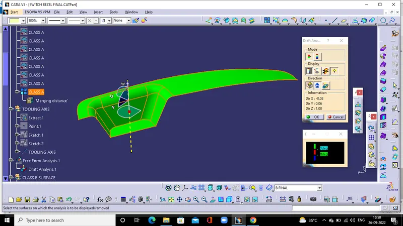
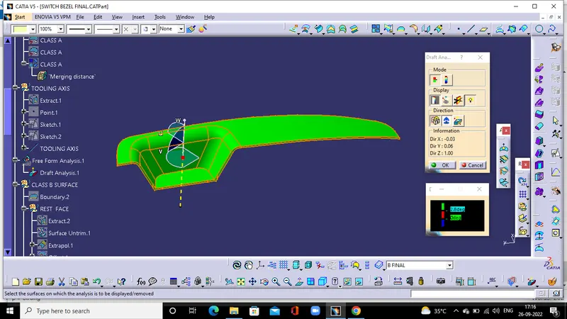
DRAFT ANALYSIS OF CLASS A
Do draft analysis of the class A and modify the sketch so that tooling axis clears the class A.
CREATION OF CLASS B SURFACE
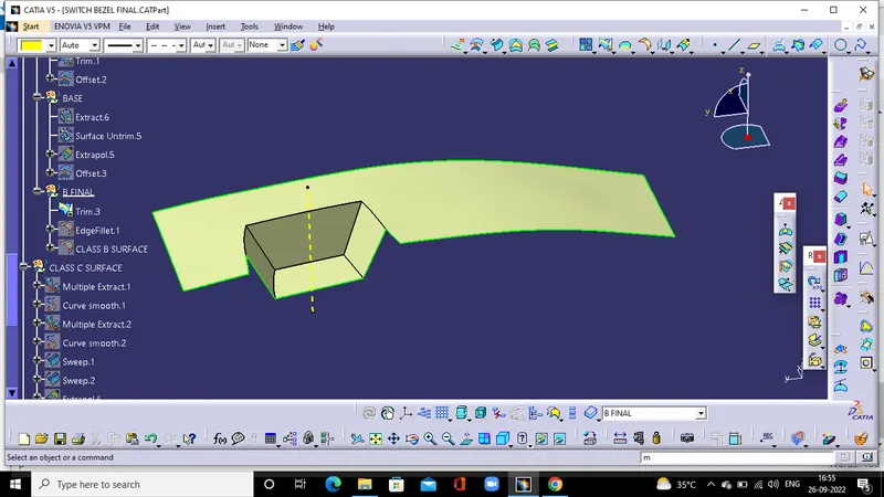
Extracting the class - A surface neglecting the fillets and then untriming and extrapolating them to join them, and after that offset the surface to 2.5 mm thickness which forms the Class - B surface.
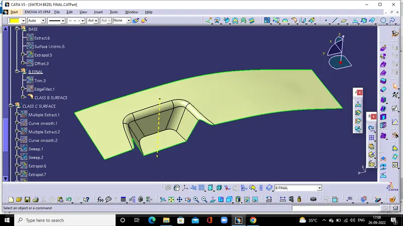
Apply edge fillet for the edges
CREATION OF CLASS C SURFACE
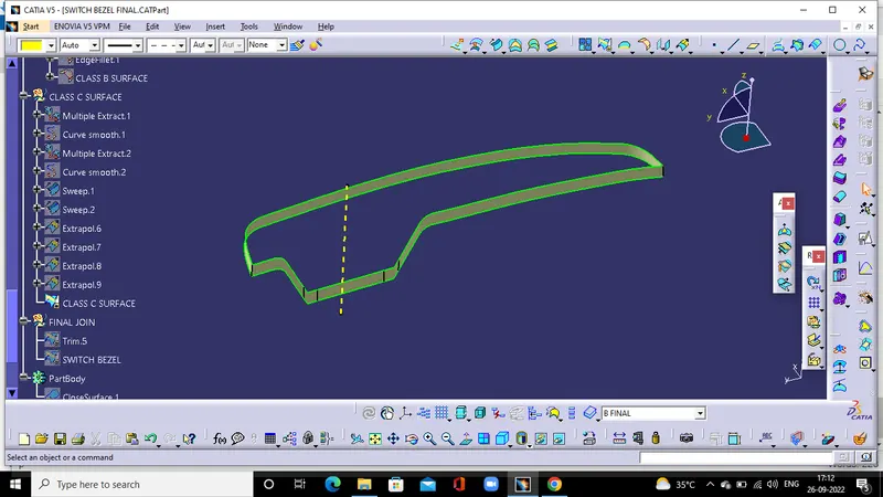
By extracting the edges of the class A suraface sweep the edge with a draft angle of 3deg along the direction of tooling axis using with draft direction option.
FINAL JOIN OF SWITCH BEZEL
Trim the class A and class C surface and trim with the class B.
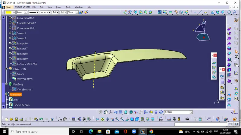
DRAFT ANALYSIS OF SWITCH BEZEL
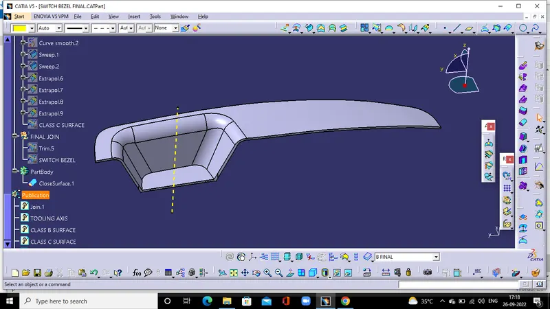
SOLID PART
In the part workbench convert the surface into solid by close suraface option.
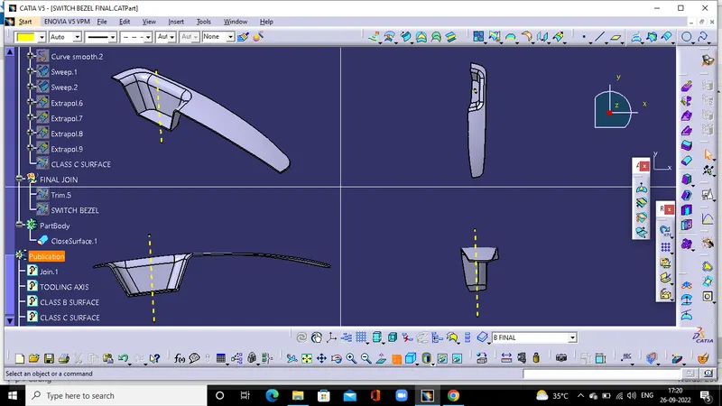
DIFFRENT VIEWS
TREE STRCTURE
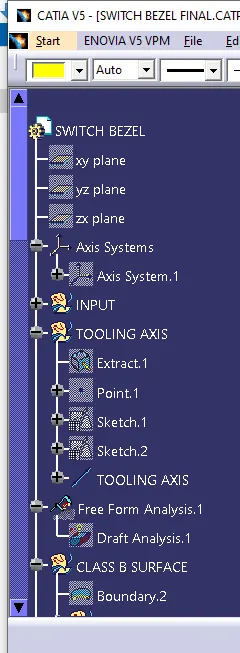
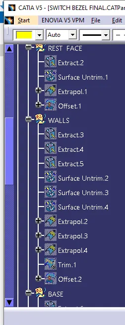
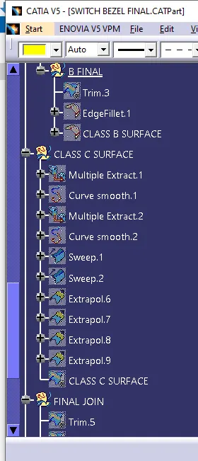
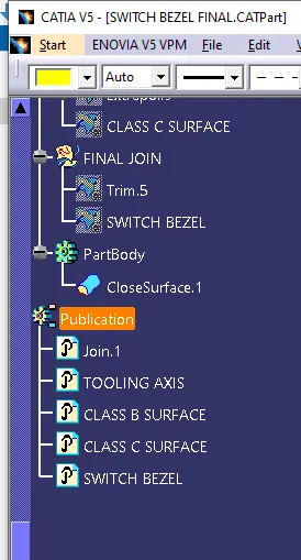
CONCLUSION
Switch bezel design has been done for the given class A by maintaining proper tree structure