Week 8 - Challenge 1 - Base Bracket Design
Base bracket design
Objective
To create the base bracket plastic component through the given class A surface.
Introduction
Class A surface
It provides aesthetic feature of a compound. The designer start working on tools by having class A surface as input.
Class B surface
This surface is obtained by offering the class A with a defined thickness. In this surface other fixing elements are also mounted.
Class C surface
This surface Connects the class A and B surface along the tooling axis.
Tooling axis
It is the direction along the core and cavity open and close. The class C is drafted along the tooling axis.
Draft analysis
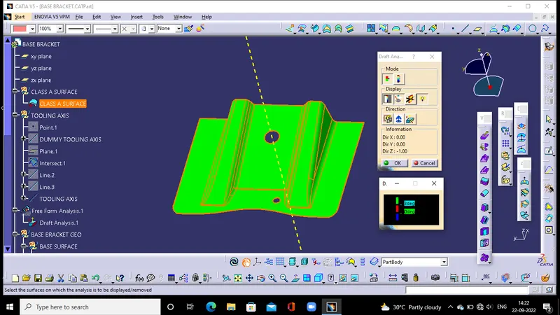
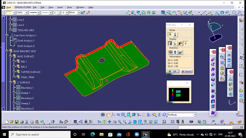
The Draft Analysis allows the user to easily analyze a part for proper draft angle. A Draft Angle describes the amount of taper for molded or cast parts perpendicular to the parting line.
The analysis use diffrent colour for the indicating angle range.
Green inducates the positive draft angle normally ranging from 0.3 to 3 deg
Red indicatesthe neutral draft angle.
Blue indicatesthe negative draft angle which mns it is not feasible.
Creating tooling axis
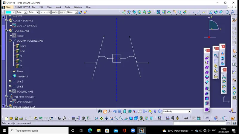
First making a point as reference create a plane. intersect the class A with the plane. Try to extent the inclined lines.
By bisecting the inclined line create a new line which is now the main tooling axis.
Creating B surface
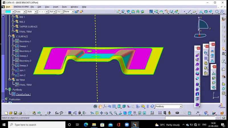
By using extract, offset and extrapolate B surface is created. This has to be done by dividing the parts of the class A and finally trim the surfaces to obtain a single B surface.
Creating C surface
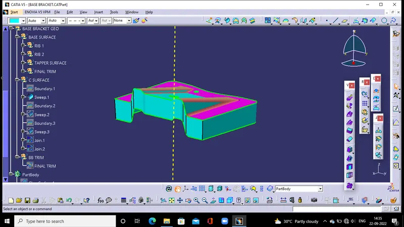
By using the sweep option C surface is created by sweeping the class A with a draft angle normally 3 deg.
Join the class A and C
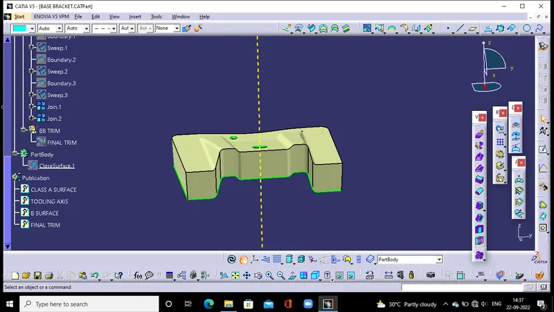
Trim it with the B surface to get the final trimmed bracket
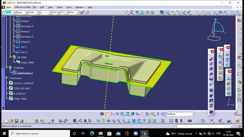
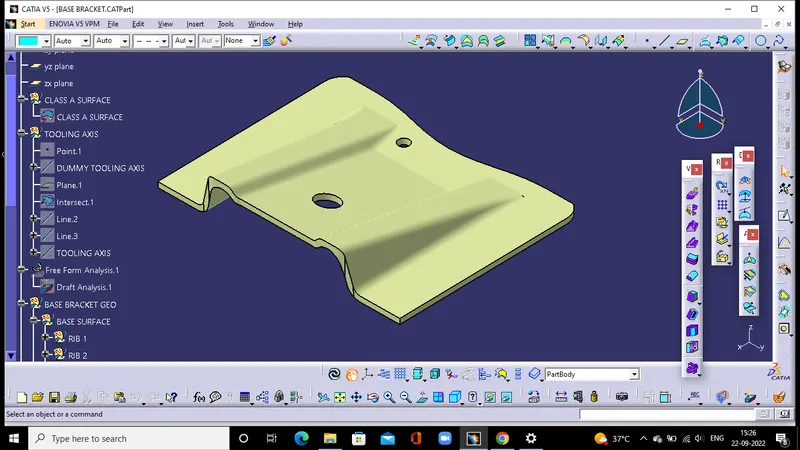
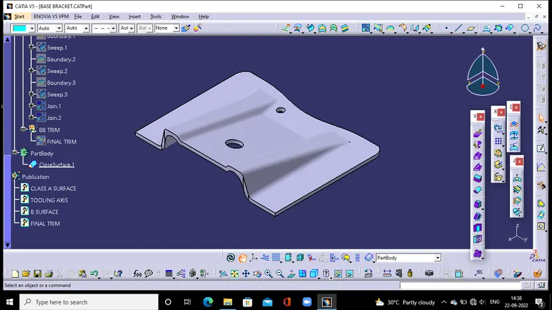
Convert the final surface to solid by using closed surface option
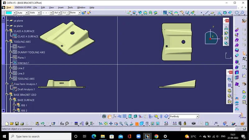
Multi view
Conclusion
Created base bracket with given class A.
Tree structure is maintained.
Tooling axis created using bisecting line.