Week 9 - Project 1 - Door Trim Lower with Engineering Features
DOOR TRIM LOWER WITH ENGINEERING FEATURES
AIM:Create the Door Trim Lower Plastic component through the given Class-A surface. To begin with, the tooling axis for the given Class-A Surface should be created meeting the requirements of the draft angle and at the end perform the Draft analysis on the model.
OPERATIONS:
CLASS A SURFACE
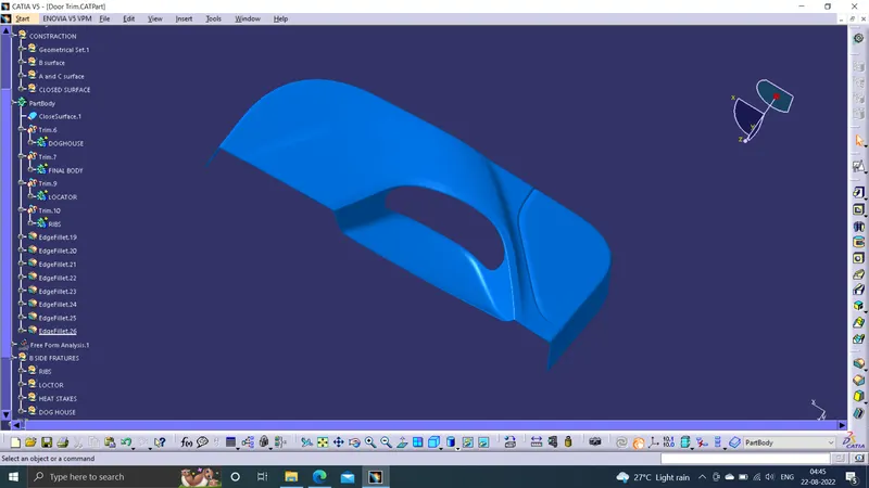
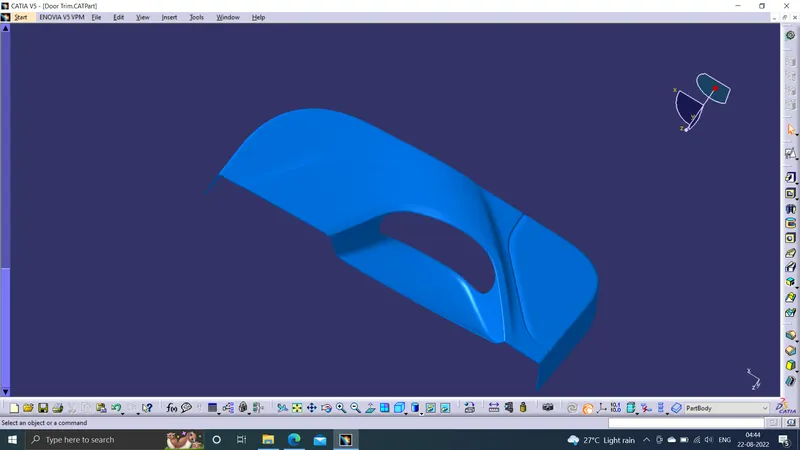
We get class A surface as a input. we create B surface and C surface using this class as a refference.
TOOLING AXIS
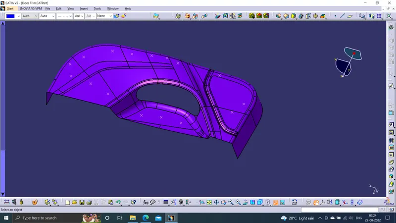
To create the tooling axis, I extracted a surface from class A and created a point in the middle of the surface by using the point command and created a line at that point through the x-axis. Now, I performed a draft analysis check from that line whether the created tooling axis is in the correct position or not. If, in the draft analysis check the surface highlighted with green colour on both sides of the surface the tooling axis is in the correct position and direction.
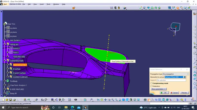
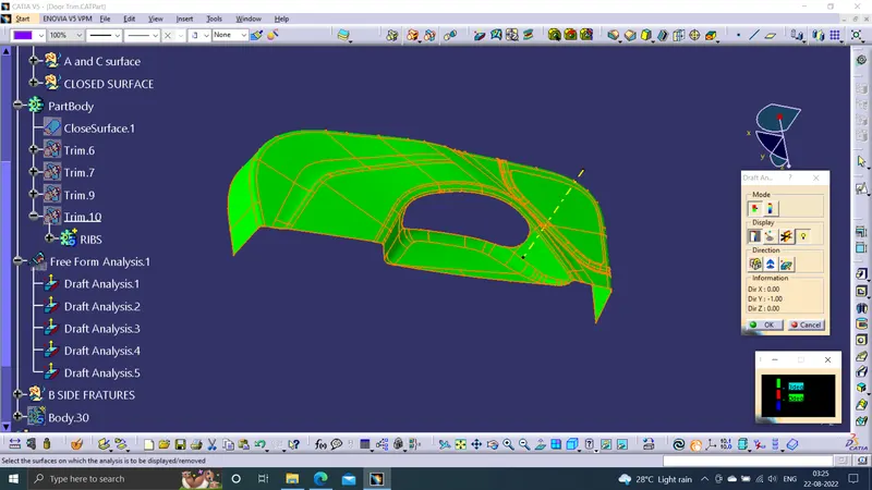
DRAFT ANALYSIS OF CLASS A
Now, I performed a draft analysis check from that line whether the created tooling axis is in the correct position or not. If, in the draft analysis check the surface highlighted with green colour on both sides of the surface the tooling axis is in the correct position and direction.
B SURFACE CREATION
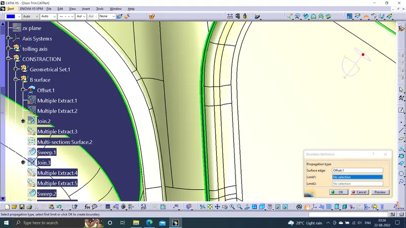
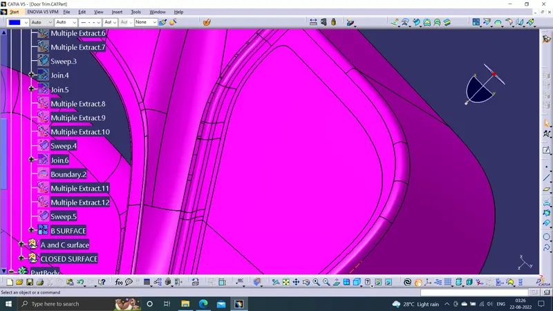
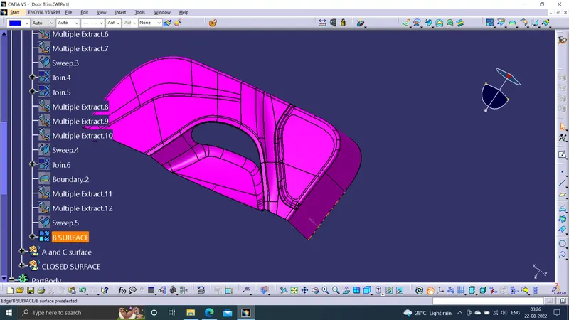
To create the class B surface, offset the class A surface inside by 3mm thickness. Once the offset is created, we can observe some patches on the offset surface, those patches are formed due to the fillets on the class A surface. We need to fill those patches with the help of the multi-section surfaces and sweep commands by extracting the patch boundaries. Once all the patches on the offset are covered properly join all the patches with the offset surface, to get the replicated surface of the class A surface.
Patches to be filled
Filled patche
C SURFACE CREATION
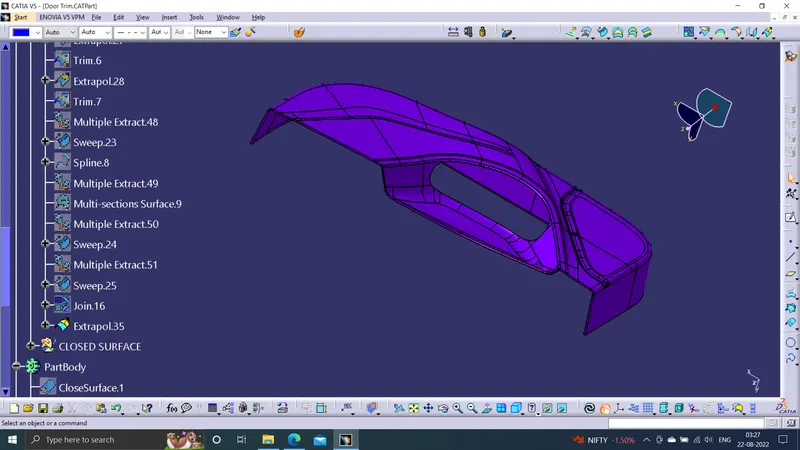
Get the boundary lines of Class A surface separately.Smooth the curves with a smooth option as boundary lines have a lot of vertices.Sweep the curves with tooling axis as direction in Sweep option.As both lines do not intersect, extrapolate them with a certain distance.Trim the surfaces.
CLOSED SURFACE
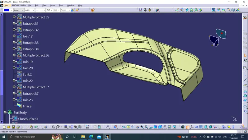
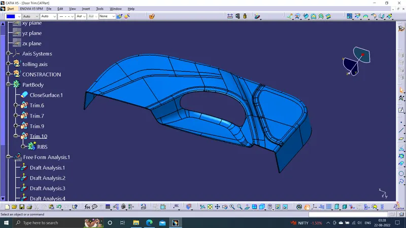
Join the Class A and Class C surfaces.Trim those joined surfaces with Class B surfaces.Go to Part Design and insert a Body and create a closed solid body from closed surface.
DRAFT ANALYSIS
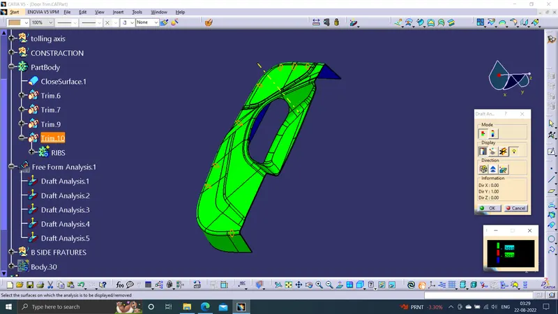
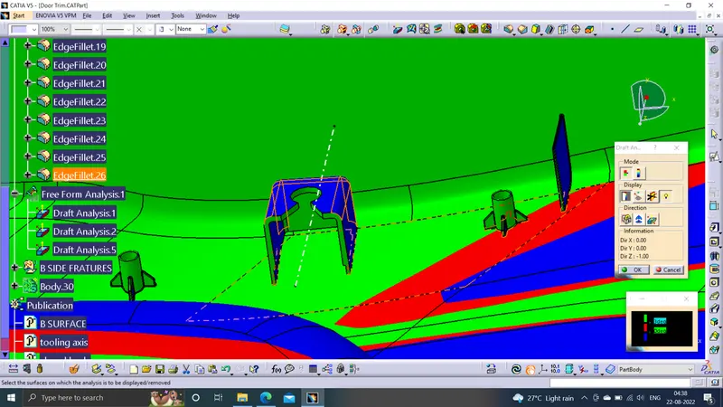
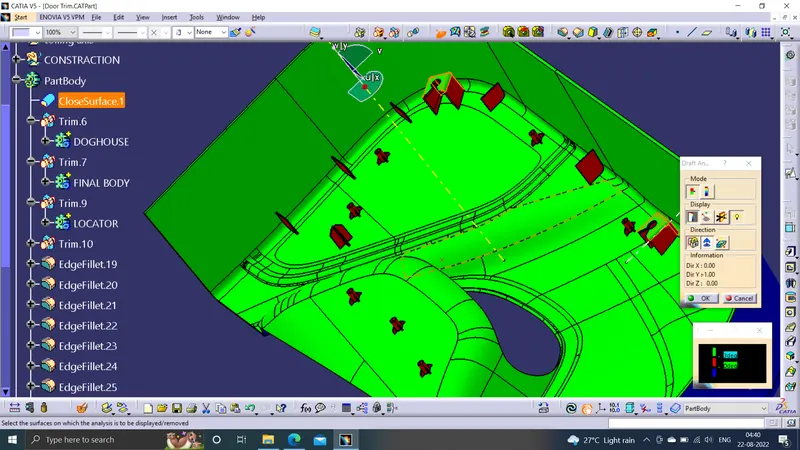
Go to the Insert menu and select the Analysis option.Select Feature Draft Analysis.Select the Material option and select the surface.Drag the compass and place on tooling axis.Make sure that the top surface is in green colour as draft angle should not exceed 3deg.Click on Okay after confirm the model.
B SIDE FEATURES
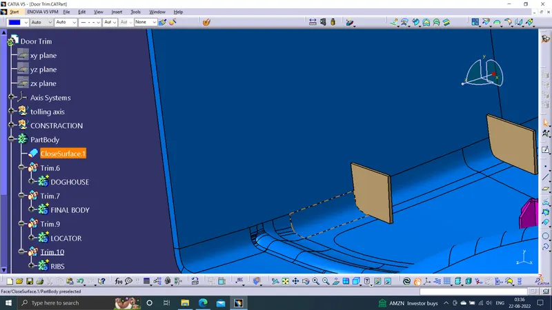
RIBS:Ribs are an essential part of plastic designing. They are instrumental in increasing the bending stiffness of plastic without increasing the thickness of its walls
HEAT STAKES
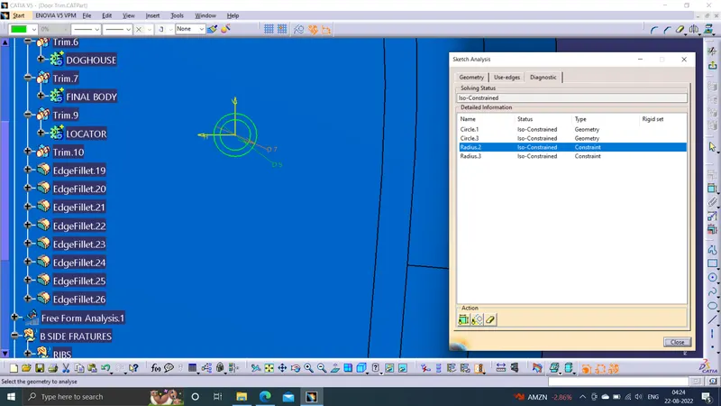
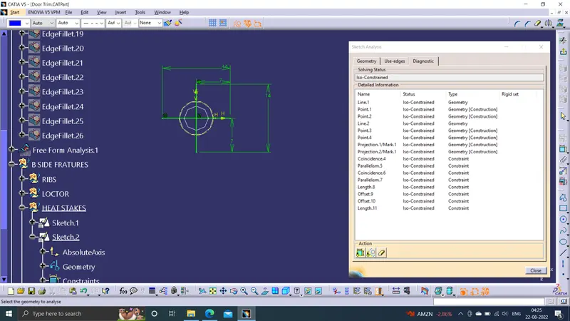
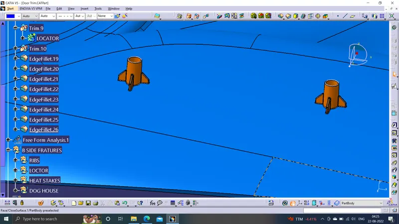
Heat staking is an assembly process that utilizes controlled melting of thermoplastic materials. A combination of pressure and heat reform plastic material to join your parts together. The results are cosmetically exceptional bonds that are indistinguishable from the original mold.
DOGHOUSE
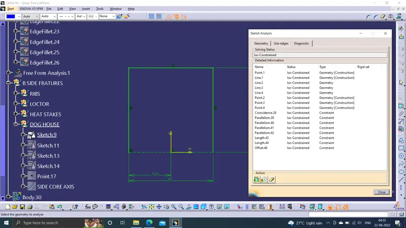
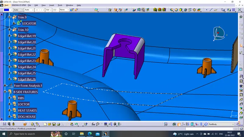
The dog house is an engineering feature used in the plastic trim design. Dog houses are used as a supporting feature. Sometimes other engineering features like snaps; locators, etc. are mounded on them to increase their strength.
LOCATOR
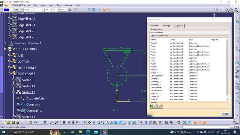
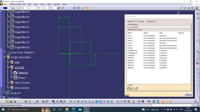
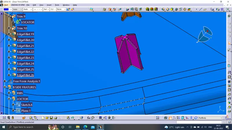
Locators are 4-way locators. The locators will follow the rib design guidelines and will be given a minimum draft of 0.5 degrees and a minimum fillet of 0.2mm and an entry chamfer of 3mm. This entry chamfer is given so that the locators can mate with the other part easily.
DTAFT ANALYSIS
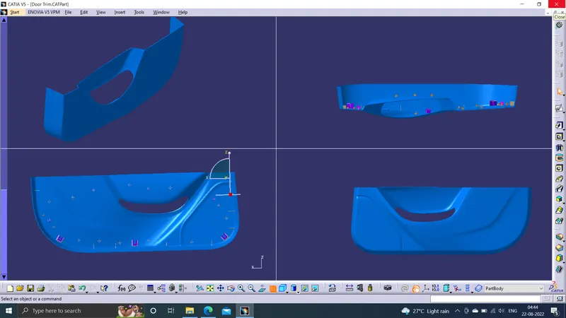
MODEL IMAGES