Week 8 - Challenge 2 - Switch Bezel Design
SWITCH BEZEL DESIGN
AIM:Create the Switch Bezel Plastic component through the given Class-A surface. To begin with, the tooling axis for the given Class-A Surface should be created meeting the requirements of the draft angle and at the end perform the Draft analysis on the model.
OBJECTIVE :
- Creation of Tooling Axis.
- Draft Analysis of Class A surface.
- Creation of Class B and Class C surface.
- Creating a solid part out of surface modelling.
- Draft Analysis of switch bezel componet.
CLASS A SURFACE
We get a class A surface as a input.
TOOLING AXIS
Extracted the base surface and center point is created by using the on surface at zero.On that point the axis system is created. make an intersection on the YZ plane to get a boundary line as a refference .Made a dummy axis line to form a tooling axis by a bisecting two lines.
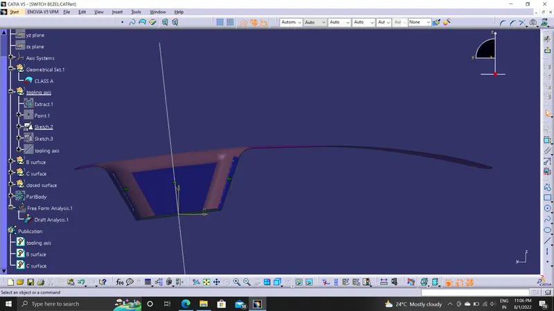
made another sketch on the XZ plane using the axis center point, a line is drawn in sketch mode and it is constrained at the angle of 6 degrees from the refference line.
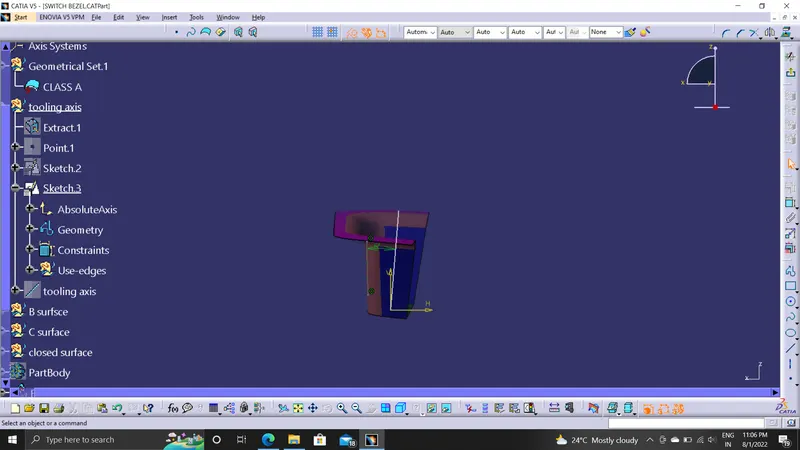
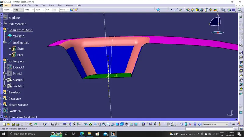
By bisecting two dummy axes we get a original tooling axis.
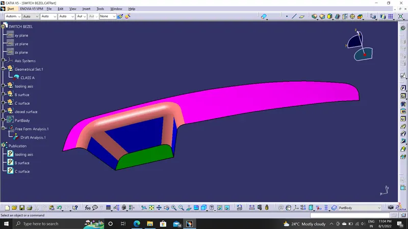
CLASS A SURFACEN ALAYSIS
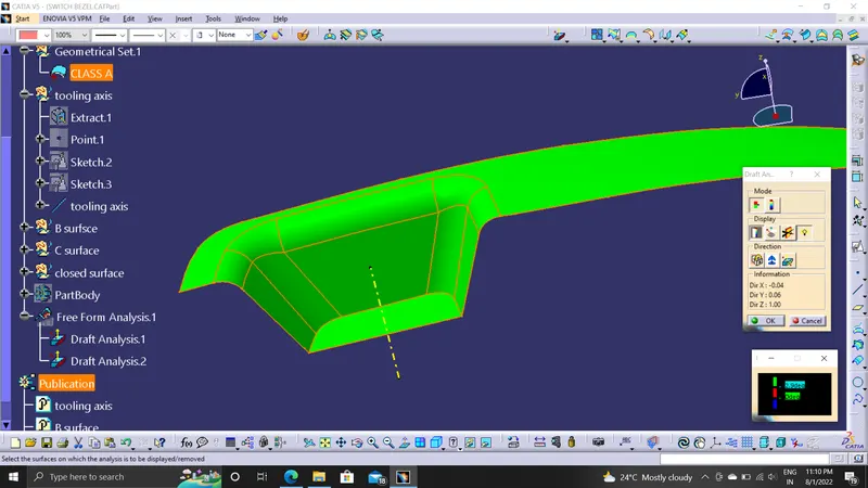
Change the shading style to "shading with material". Select the Feature draft analysis. Select compass icon in draft analysis dialogue box and drag the compass and place it on tooling axis and select lock draft direction option. Swith to quick analysis mode to see whether the surfaces are passed draft angles or not.
CLASS B SURFACE
The class B surface is created by extracting each surface of class A surface and then untriming them.
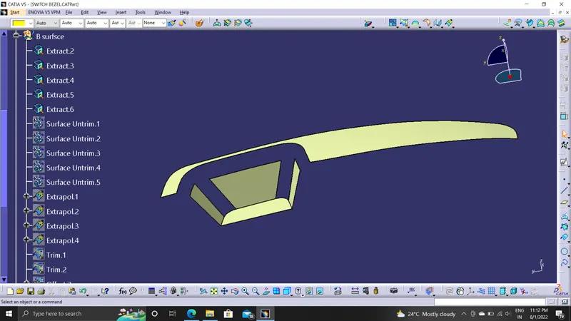
And then we offset with required thickenss is given in the downward direction.
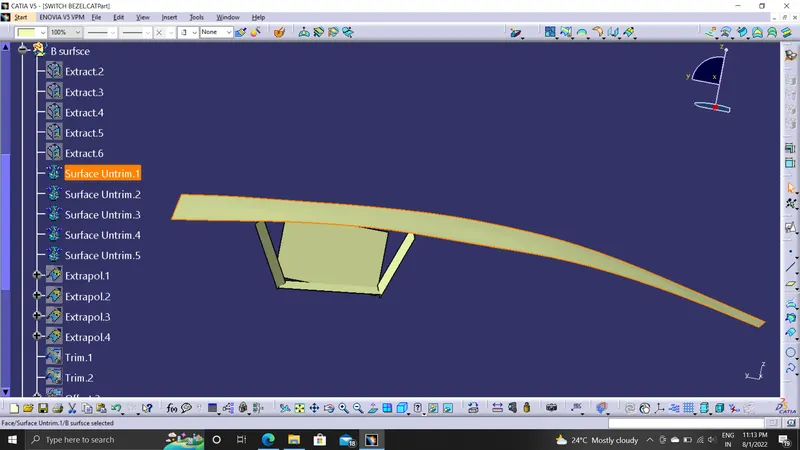
The surfaces are then extrapolated with a certain distance in order to create cross section among the surfaces to perform trim operation to generate the class B surface.
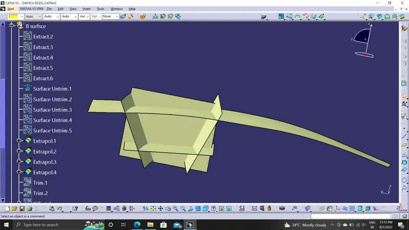
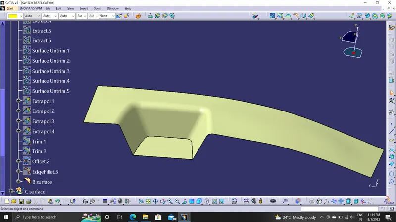
CLASS C SURFACE
For the creation of class C surface, first the boundary of the class A surface is extracted using Multiple extract feature.
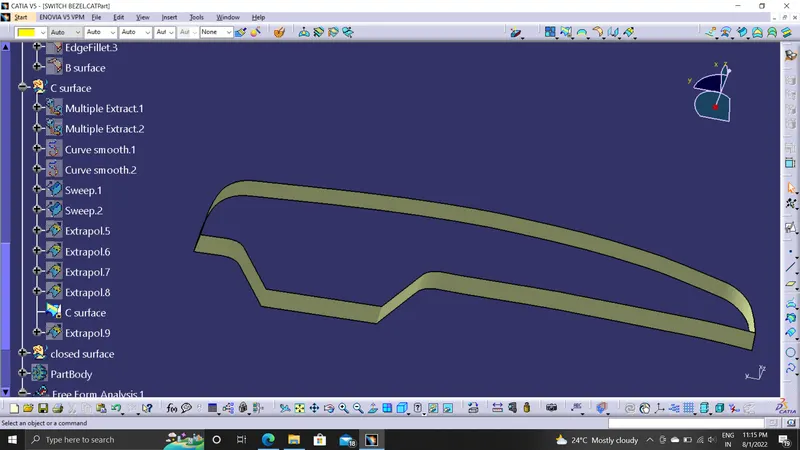
After this sweep option is used to create the sweep along the tooling axis direction.
CLOSED SURFACE
Class A surface and the class C surface are then joined together to get desired shape
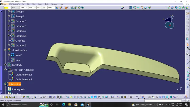
After this operation, class B and joined surface are trimmed together to give the plastic product a mouldable shape.
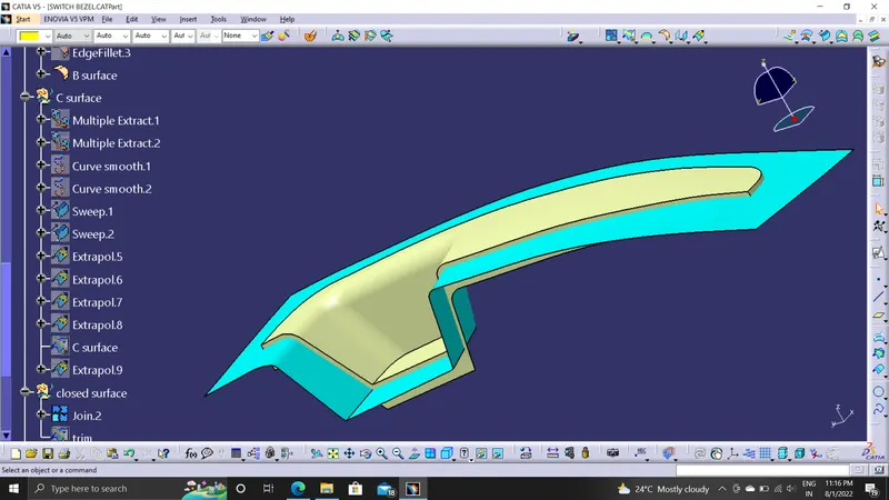
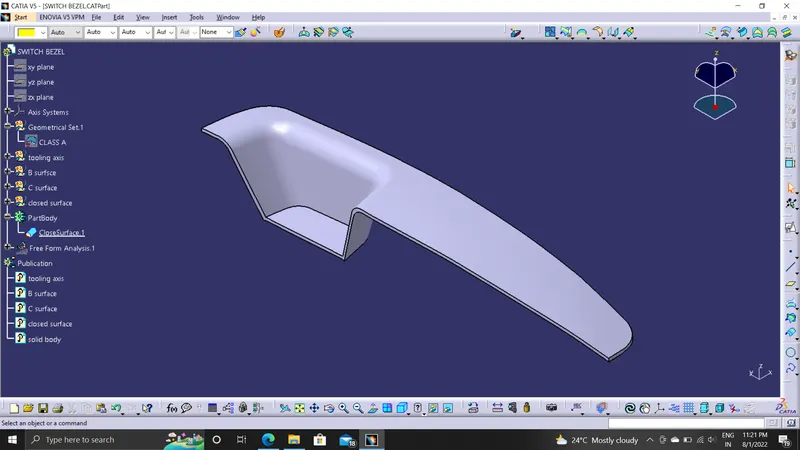
After ensuring that the surfaces formed are completely closed, the closed surface feature is used to create the solid mould of the switch bezel
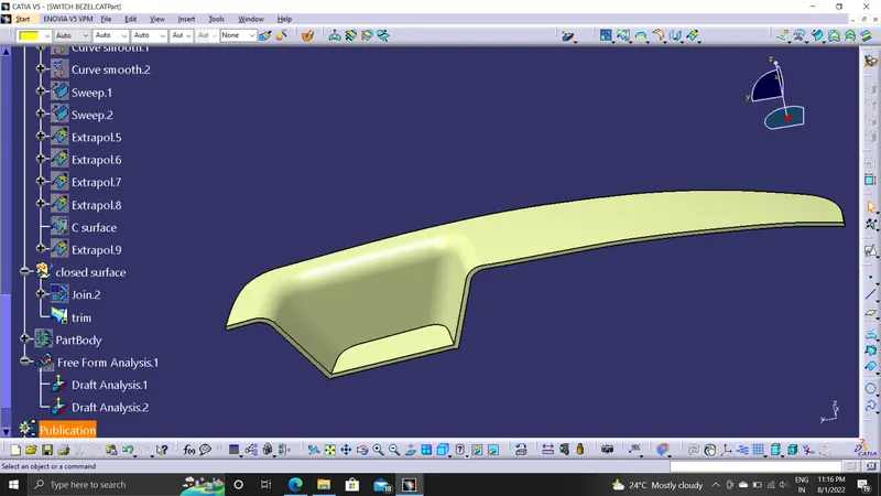
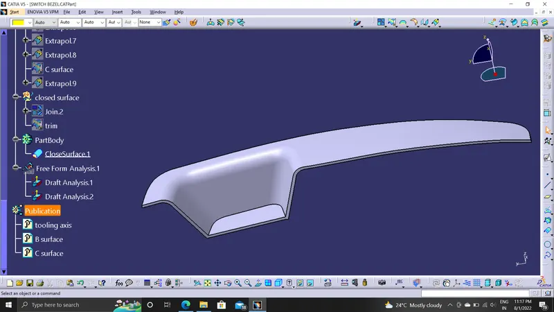
ANALYSIS
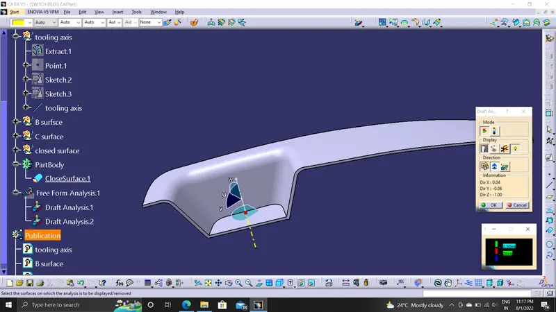
The part created has to be changed to material mode in display frame. Then by enabling compass definition the axis system is pan along the direction of the part and aligned in line with the tooling direction Lock Direction is applied that fixes the compass and then the mode dialog box is formed by snapping at any point on the part .The Color Codes are classified and Draft Angle are applied
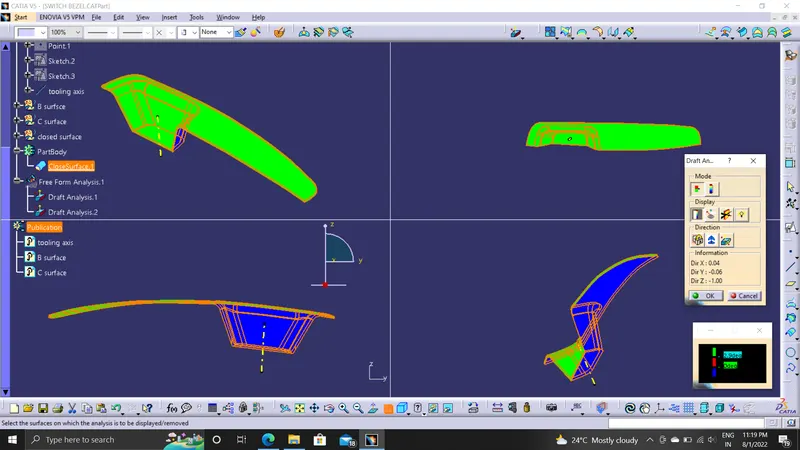
RESULTS
Created of Tooling Axis.
Draft Analysis of Class A surface is done .
Created of Class B and Class C surface .
Created a solid part out of surface modelling.
Draft Analysis of switch bezel componet is done.