Week 11 - Final project
DOOR PANEL
AIM : To create the Door trim panel's CAD model considering the inputs such as class A surface and master section and by following the design rules and OEM standards.
INTRODUCTION
The door panel covers internal parts like the window regulator, the power window motor, and the wiring. In older cars, door panels used to be made out of cardboard and upholstered with material that matches the rest of the upholstery within the cabin.
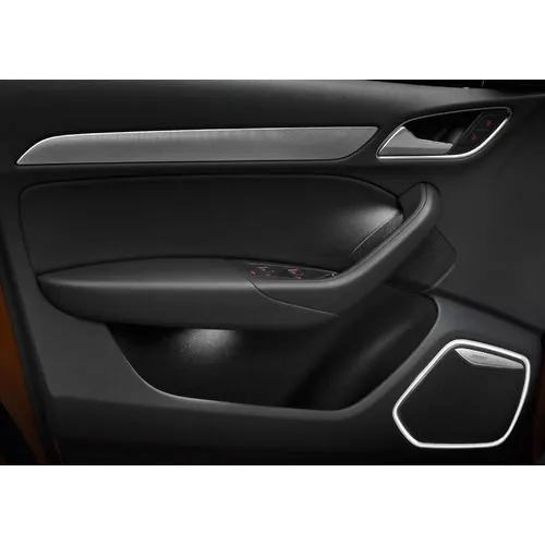
CLASS A SURFACE
We get class A surface as a input. we create B surface and C surface using this class as a refference.
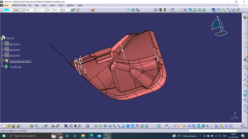
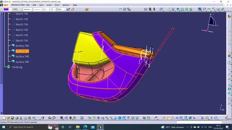
In the above fig.,we can see that the surfaces along with the master section are given.
so here I have to create three parts that are mentioned below:
1) Lower substrate
2) Map pocket
3) Bottle Holder
4) Door Armrest
Then I have to create the attachment features that are required for the assembly of the parts.
LOWER SUBSRTACT
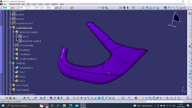
Extract the Lower substrate clacss A surface
MODIFIED CLASS A SURFACE
TOOLING AXIS
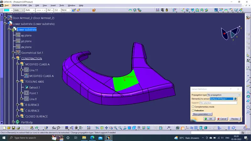
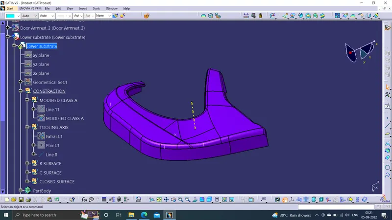
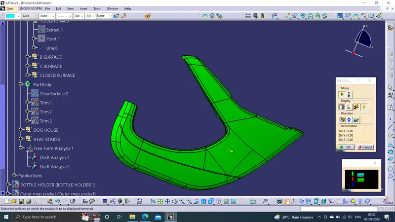
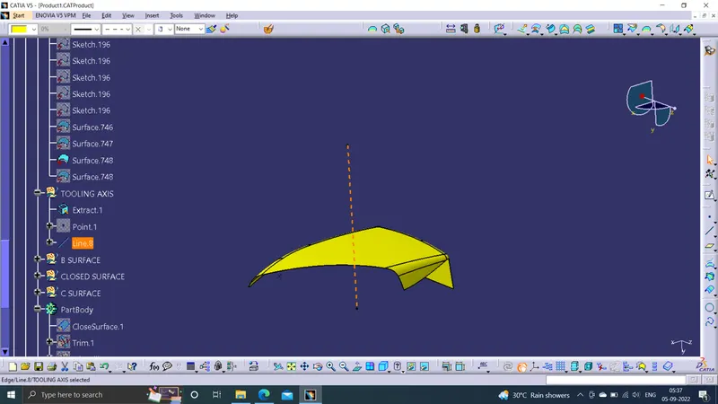
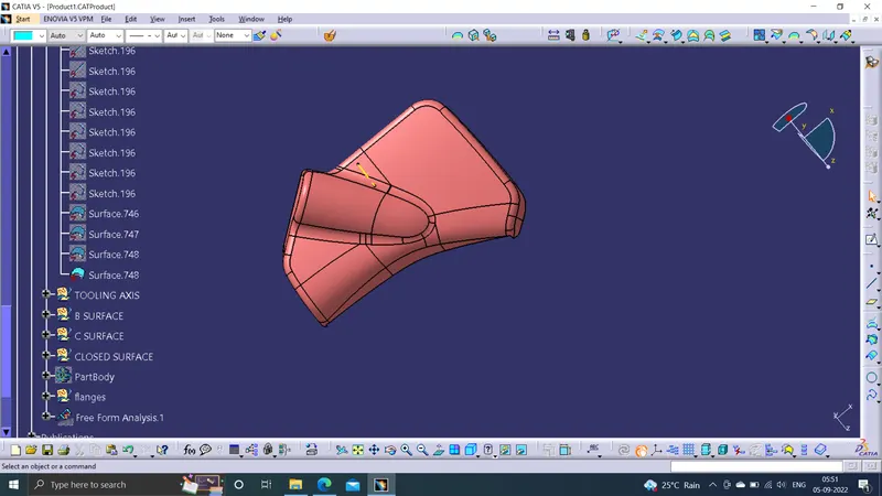
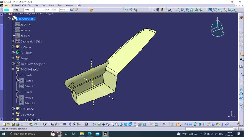
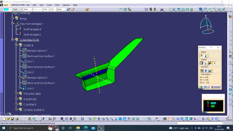
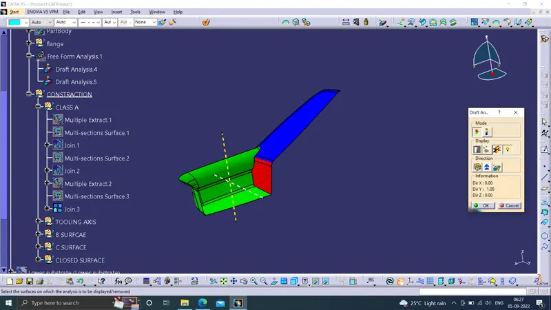
To create the tooling axis, I extracted a surface from class A and created a point in the middle of the surface by using the point command and created a line at that point through the x-axis. Now, I performed a draft analysis check from that line whether the created tooling axis is in the correct position or not. If, in the draft analysis check the surface highlighted with green colour on both sides of the surface the tooling axis is in the correct position and direction.
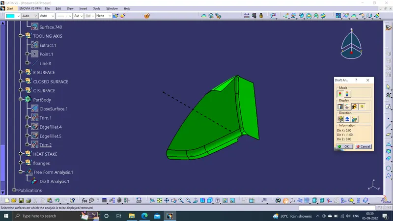
DRAFT ANALYSIS OF CLASS A
Now, I performed a draft analysis check from that line whether the created tooling axis is in the correct position or not. If, in the draft analysis check the surface highlighted with green colour on both sides of the surface the tooling axis is in the correct position and direction.
B SURFACE CREATION
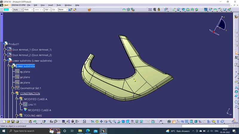
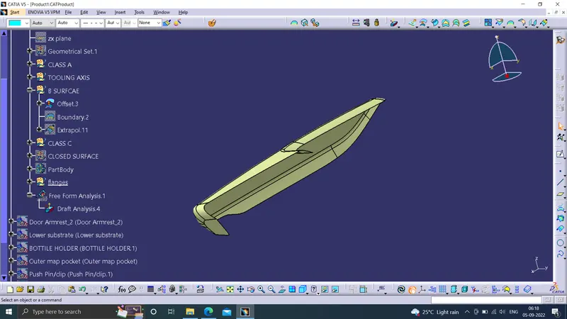
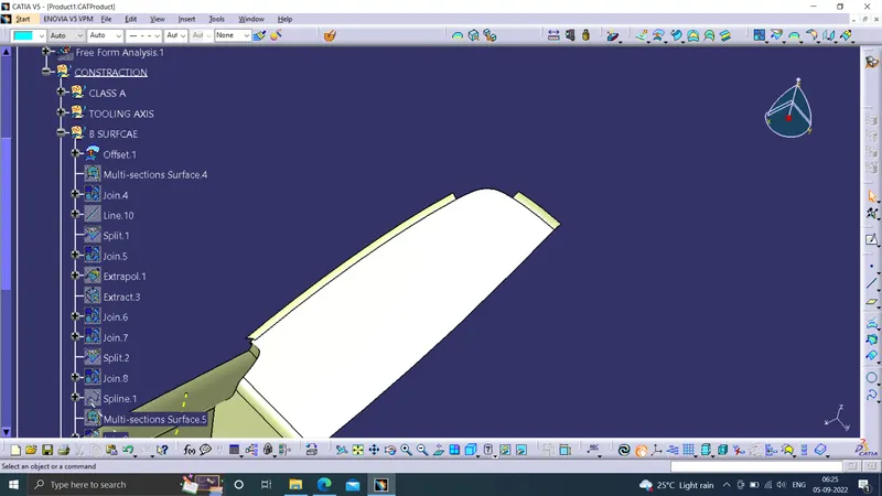
To create the class B surface, offset the class A surface inside by 2.5mm thickness. Once the offset is created
C SURFACE CREATION
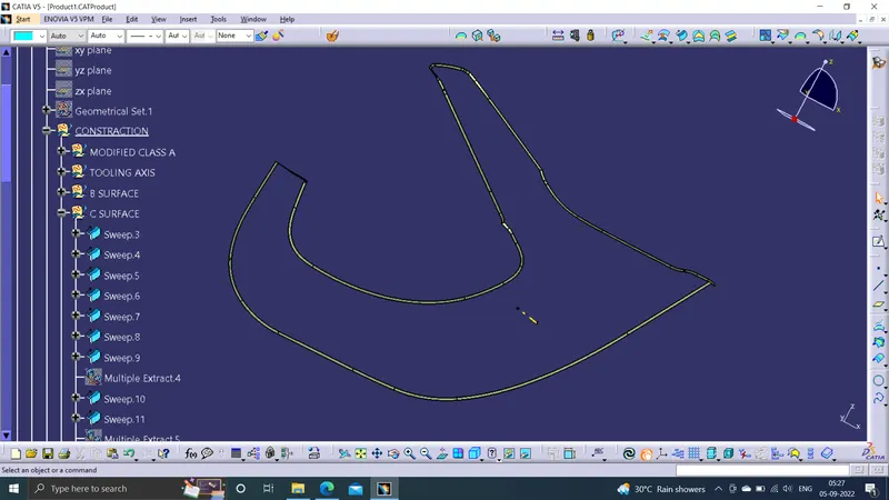
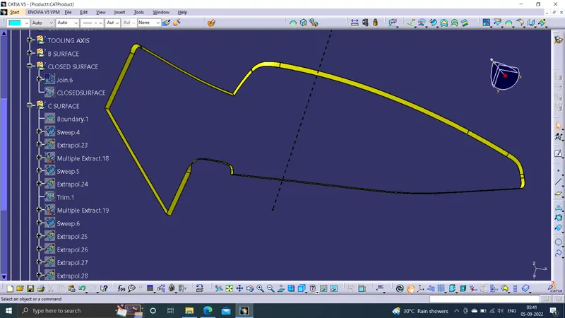
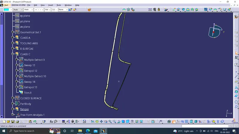
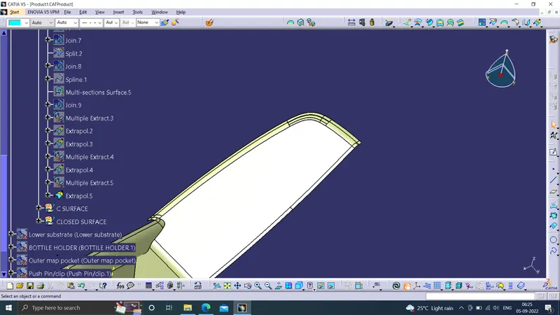
Get the boundary lines of Class A surface separately.Smooth the curves with a smooth option as boundary lines have a lot of vertices.Sweep the curves with tooling axis as direction in Sweep option.As both lines do not intersect, extrapolate them with a certain distance.Trim the surfaces.
CLOSED SURFACE
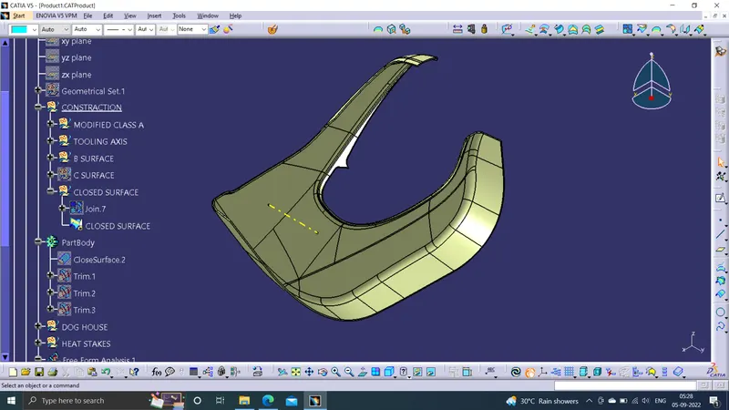
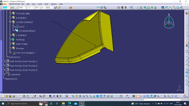
Join the Class A and Class C surfaces.Trim those joined surfaces with Class B surfaces.Go to Part Design and insert a Body and create a closed solid body from closed surface.
DRAFT ANALYSIS
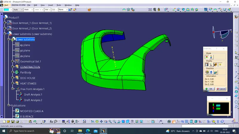
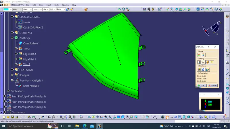
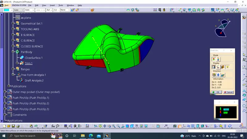
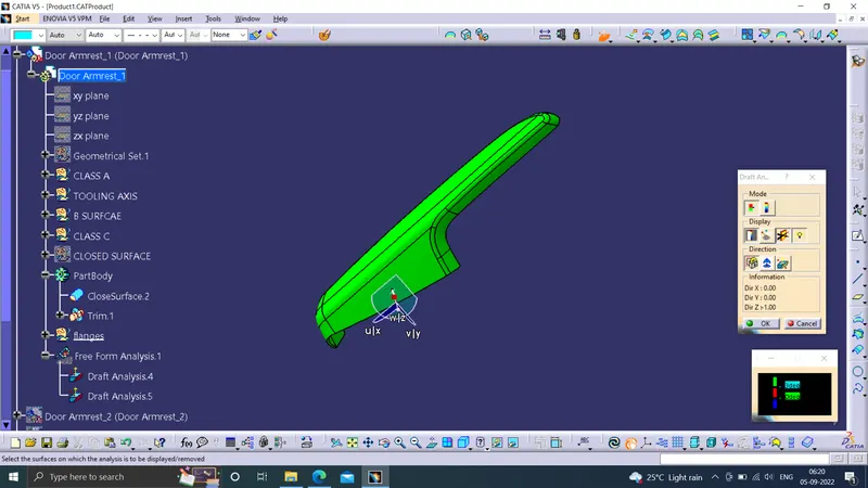
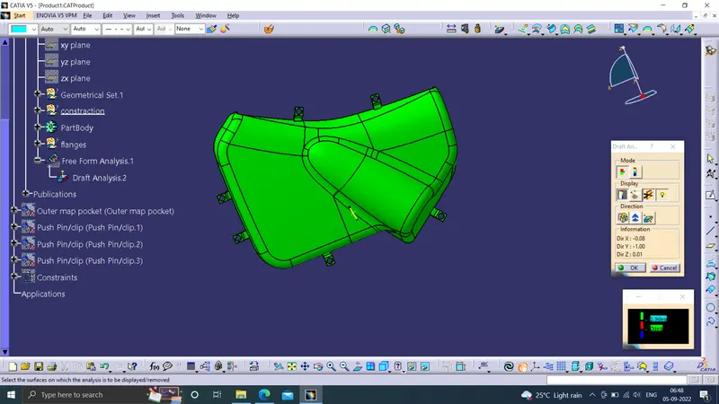
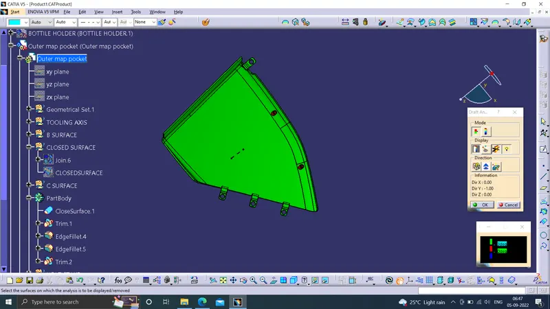
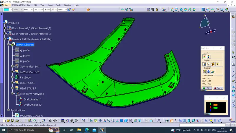
Go to the Insert menu and select the Analysis option.Select Feature Draft Analysis.Select the Material option and select the surface.Drag the compass and place on tooling axis.Make sure that the top surface is in green colour as draft angle should not exceed 3deg.Click on Okay after confirm the model.
Simmilarly
I created the other surfaces
OUTER MAP POCKET
CLASS A
TOOLING AXIS
DRAFT ANALYSIS OF CLASS A
B SURFACE CREATION
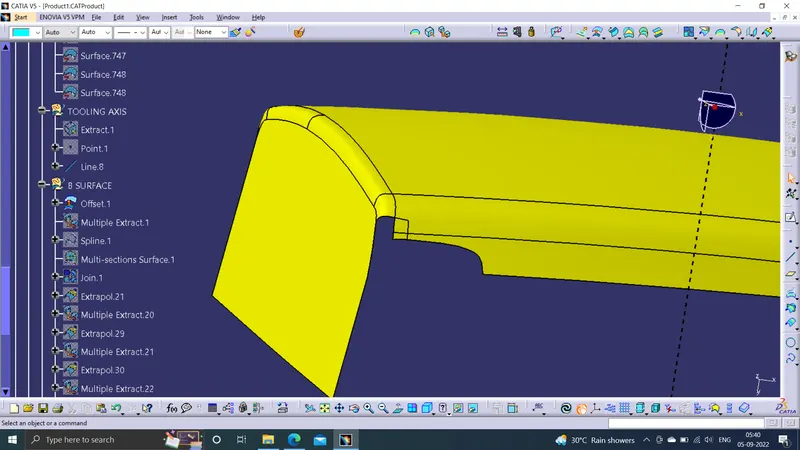
missing patch
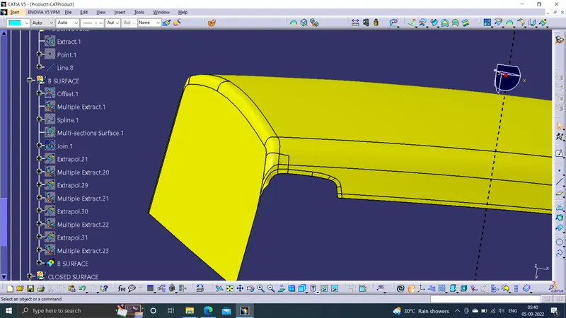
filled patch
C SURFACE CREATION
CLOSED SURFACE
DRAFT ANALYSIS
BOTTLE HOLDER
CLASS A
TOOLING AXIS
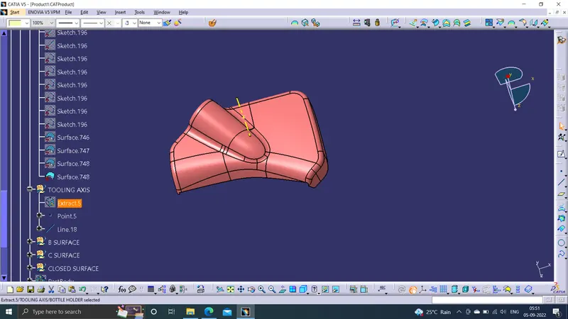
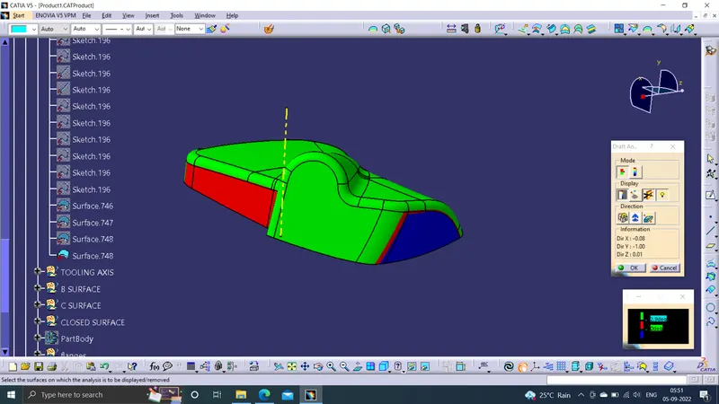
DRAFT ANALYSIS OF CLASS A
We an observe at some faces on class A has less than 1 degree draft angle , this may cause to manufacturing defects.
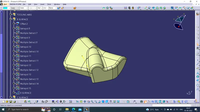
B SURFACE CREATION
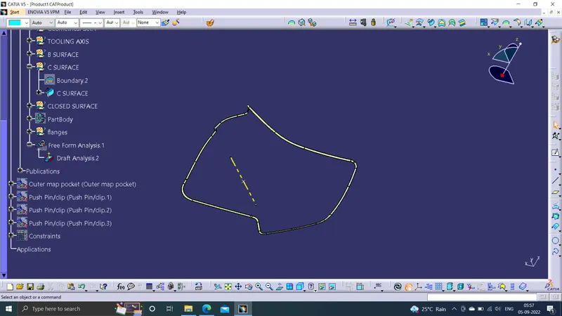
C SURFACE CREATION
CLOSED SURFACE
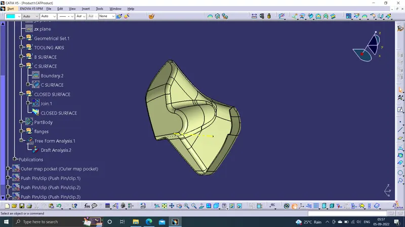
DRAFT ANALYSIS
DOOR ARMREST
I was divided the door arm rest in to two parts because of negative negative draft angle present on many paces
part _1
CLASS A
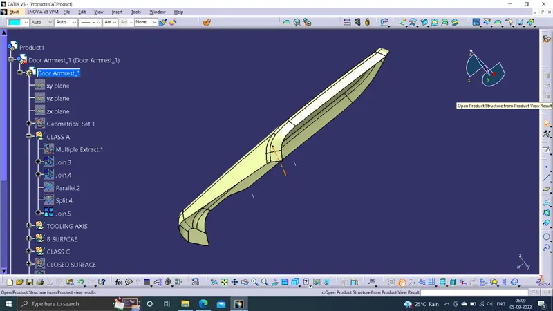
TOOLING AXIS
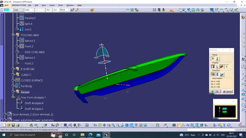
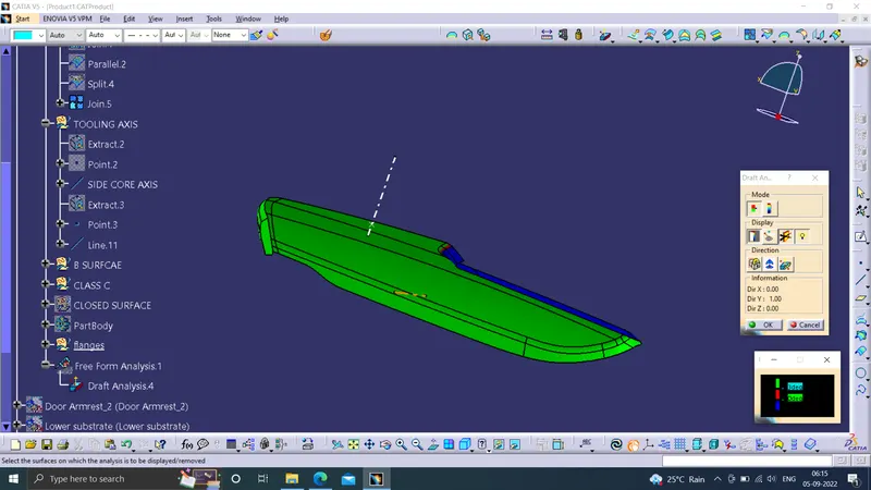
I created two tooling axis, one is normal tooling axis and other is side core axis to avoid negarive draft
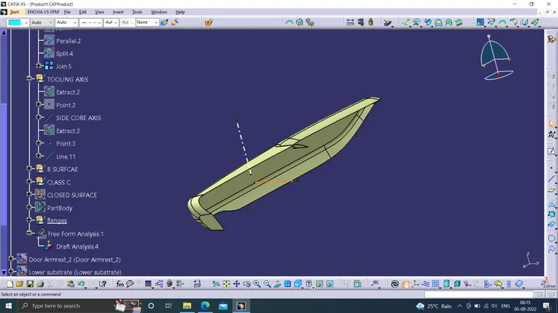
DRAFT ANALYSIS OF CLASS A
B SURFACE CREATION
C SURFACE CREATION
CLOSED SURFACE
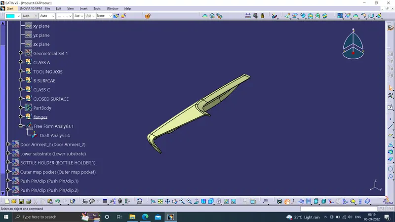
DRAFT ANALYSIS
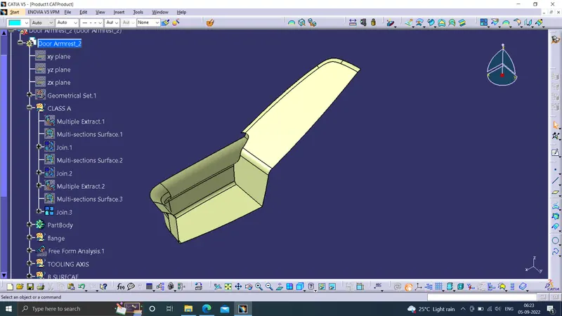
Part_2
class A
TOOLING AXIS
DRAFT ANALYSIS OF CLASS A
B SURFACE CREATION
C SURFACE CREATION
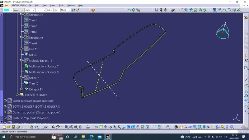
CLOSED SURFACE
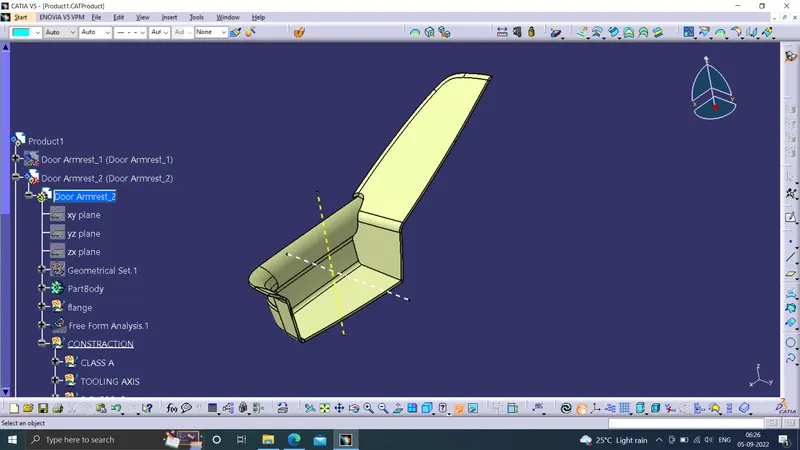
DRAFT ANALYSIS
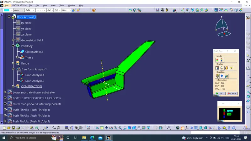
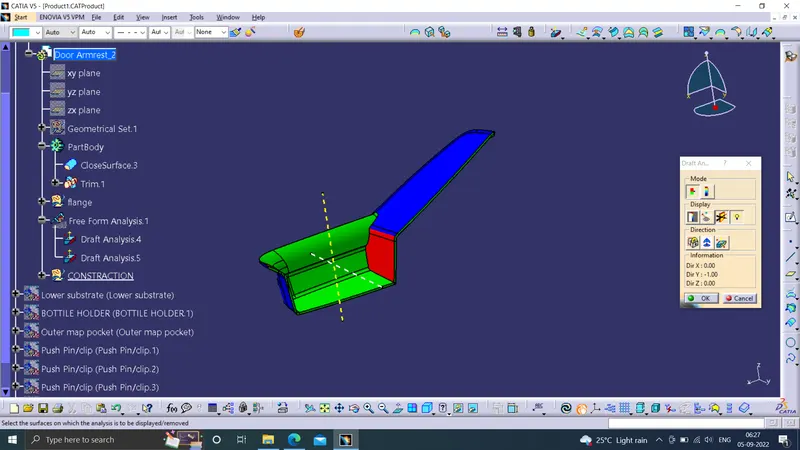
we can clear the less than 1 degree draft angle with this side core axis.
B SIDE FEATURES
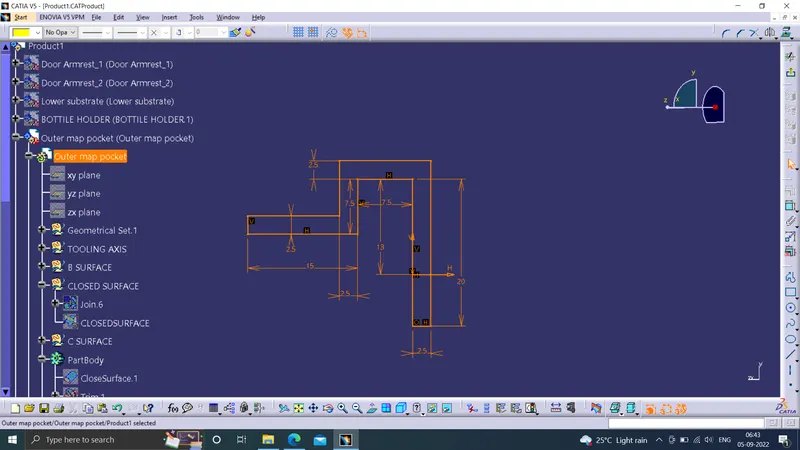
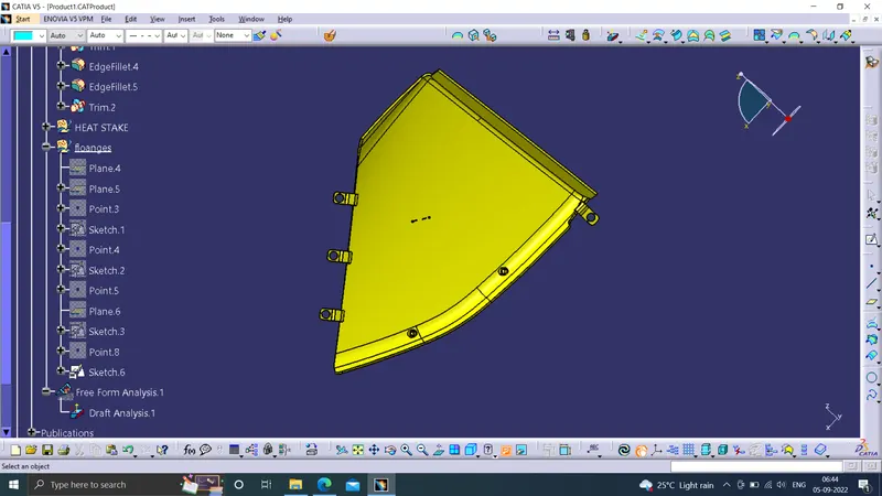
FLANGES - Flanges are the elements that are needed to join different components together. So here I have to make flanges on the door armrest and the map pocket. Following the master section, given as the input basically the measurements and location of the flange.I have created the flanges. First I have created the flange on the outer map pocket. For creating the flanges I have taken extraction of the curve and made a point on that curve then created one plane on that point followed by creating a sketch on that plane taking the point created as the origin
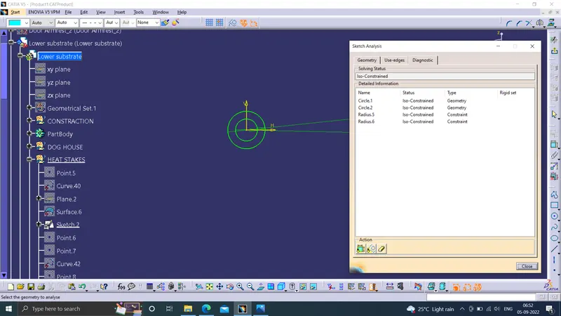
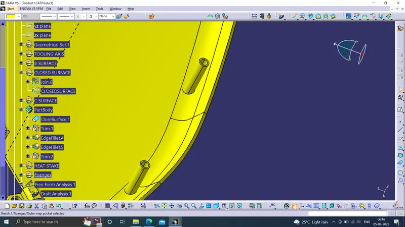
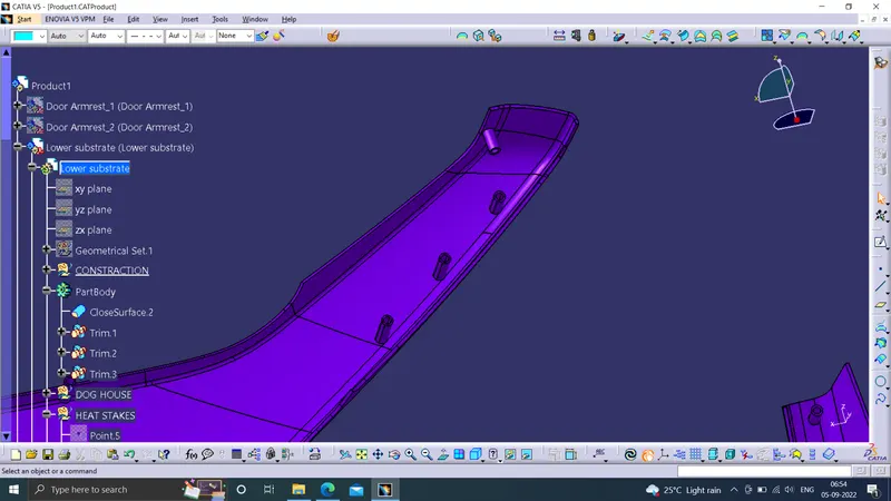
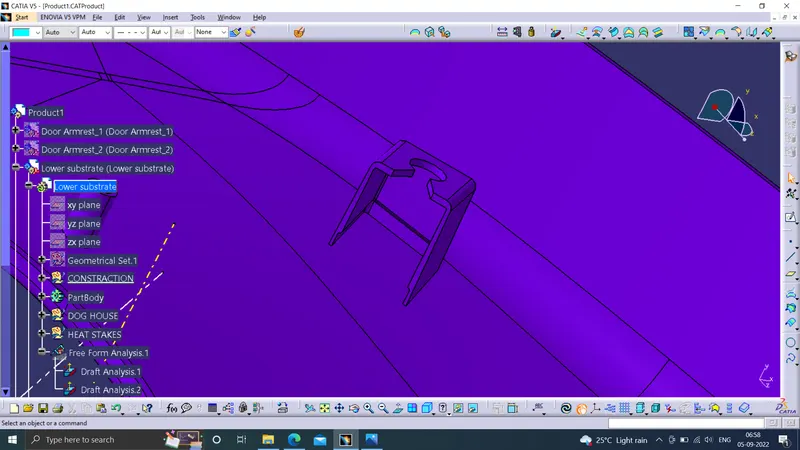
HEAT STAKES
Heat staking is an assembly process that utilizes controlled melting of thermoplastic materials. A combination of pressure and heat reform plastic material to join your parts together. The results are cosmetically exceptional bonds that are indistinguishable from the original mold.
DOGHOUSE
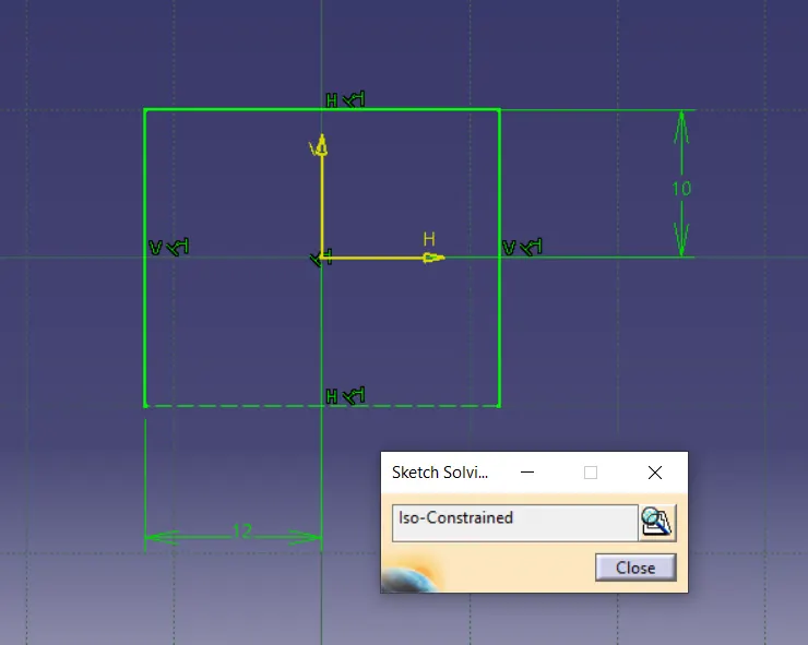
The dog house is an engineering feature used in the plastic trim design. Dog houses are used as a supporting feature. Sometimes other engineering features like snaps; locators, etc. are mounded on them to increase their strength.
DRAFT ANALYSIS
PUSH PIN:
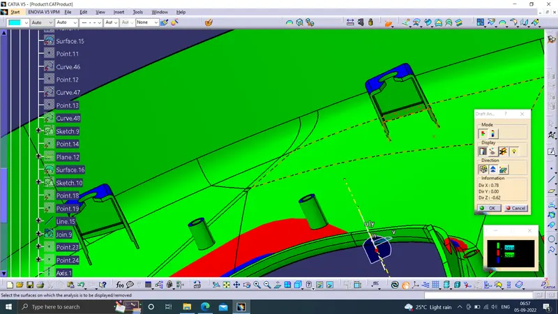
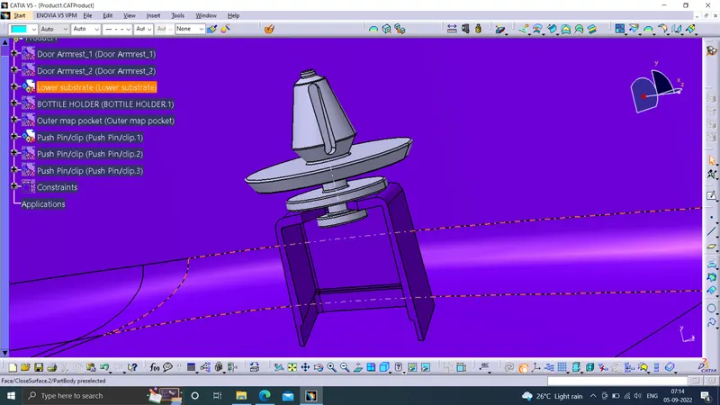
Push pins are used for joining one component to another. These are basically attached to the dog house
i created push pin by remastering method with help of dump solid.
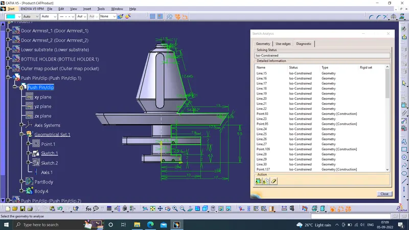
by shaft we get the solid from the above sketch.
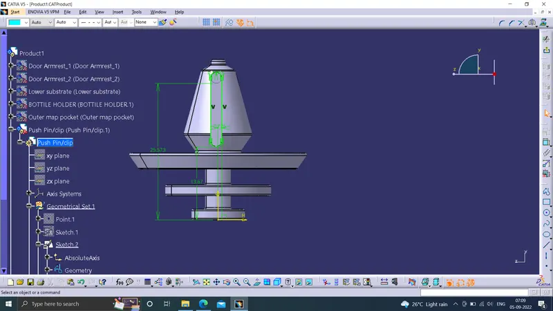
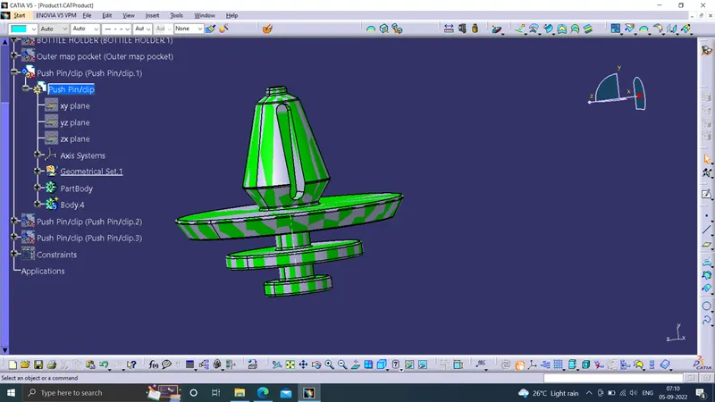
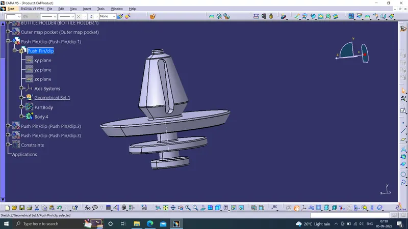
copy and past the push pin in assembly workbench and then constarined with doghouse.
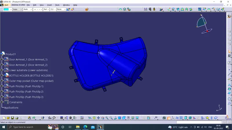
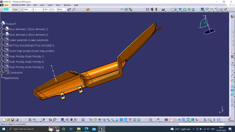
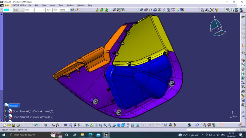
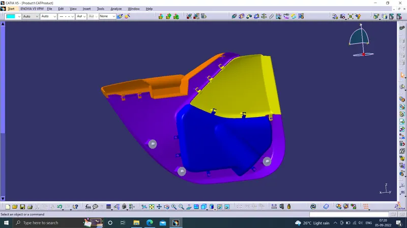
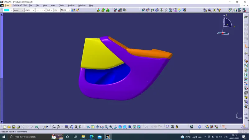
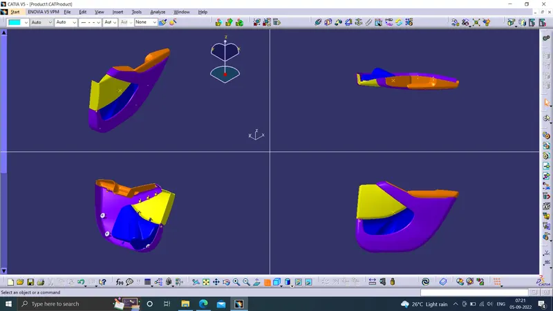
some of model images:
RESULT:
The creation of the Door Panel along with engineering features using the master section given as the input and the draft analysis has also been performed on the component.