Week 9 - Project - A pillar Design with Master Section
A-PILLER DESIGN WITH MASTER SECTION
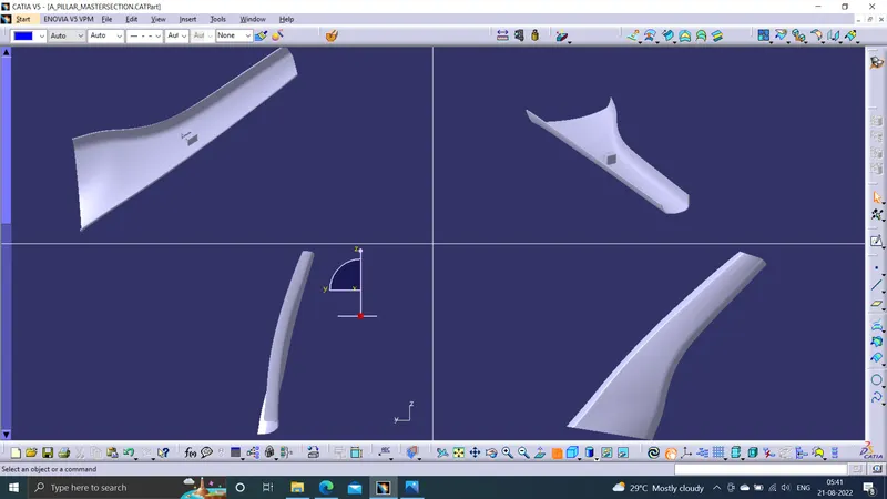
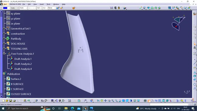
AIM:The main objective of this challenge is to understand the given master section to create a solid body and B-side features for a given class A surface, by considering all the design parameters.
OPERATIONS
MASTERSECTION
We get class A surface with master section as a input. we create B surface and C surface using this class as a refference and also create B side features using given mastersection.
TOOLING AXIS
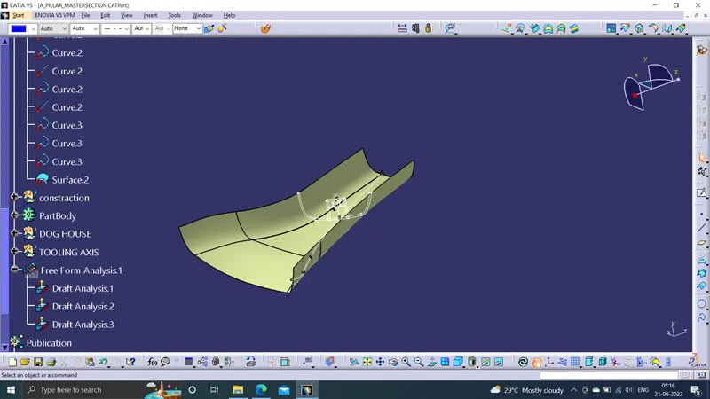
To create the tooling axis, I used the 'bisecting' line method. Initially, I created two lines on the master section by using 'point to point line' and then I created a bisecting line at the centre of those two lines by using bisecting line option in the line command.
DRAFT ANALYSIS OF CLASS A
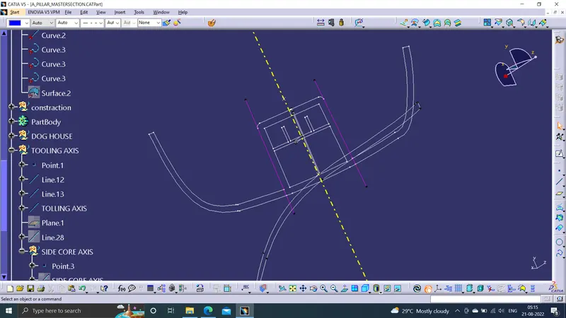
Now, I performed a draft analysis check from that line whether the created tooling axis is in the correct position or not. If, in the draft analysis check the surface highlighted with green colour on both sides of the surface the tooling axis is in the correct position and direction.
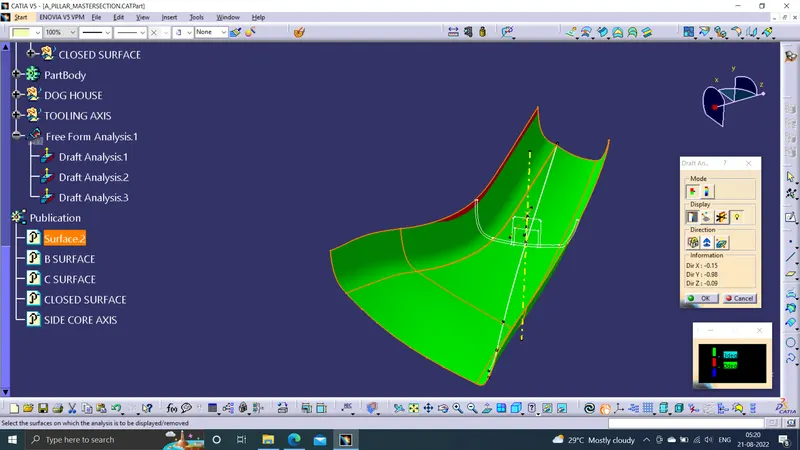
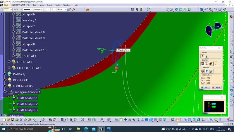
Minimum draft angle on the class a surface is 2.2 degrees
B SURFACE CREATION
To create the class B surface initially, I measured the thickness of the master section (2.5mm). I offset the class A surface 2.5mm to the inside direction. The styling fillets on the class A surface are not offset properly, it created the patch on the offset surface. I used the sweep command to close the patch on the offset surface.
Offset patch:
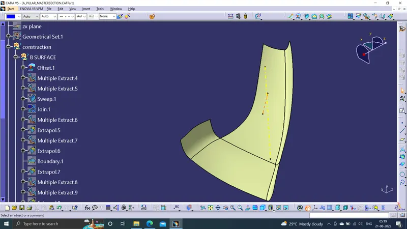
I extracted the edges of the patches, to give as a sweep command's guide curves to close the patch.
C SURFACE CREATION
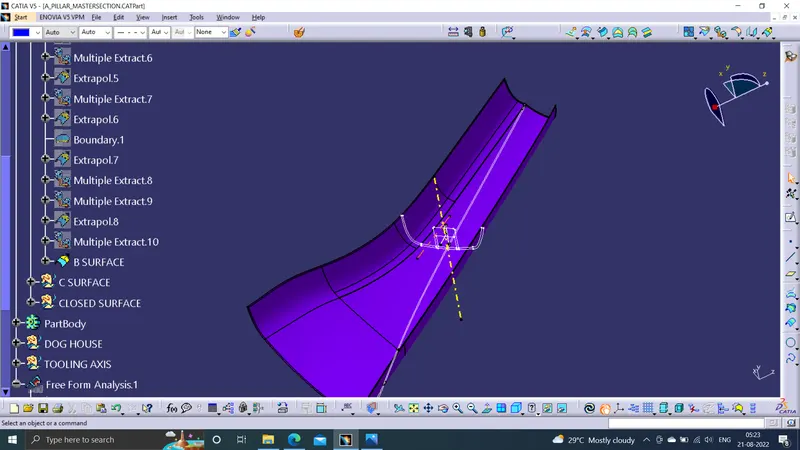
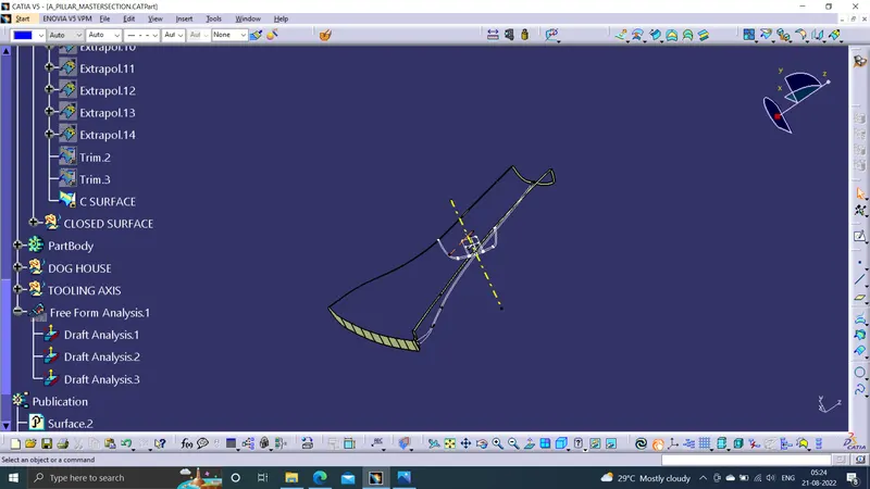
Get the boundary lines of Class A surface separately.Smooth the curves with a smooth option as boundary lines have a lot of vertices.Sweep the curves with tooling axis as direction in Sweep option.As both lines do not intersect, extrapolate them with a certain distance.Trim the surfaces.
CLOSED SURFACE
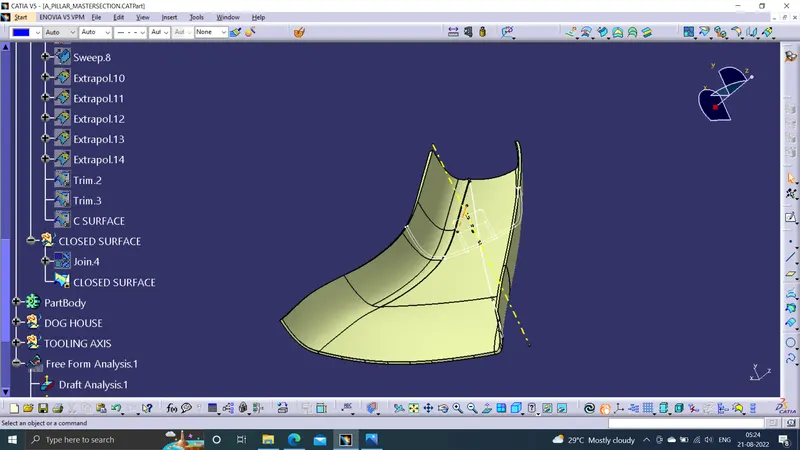
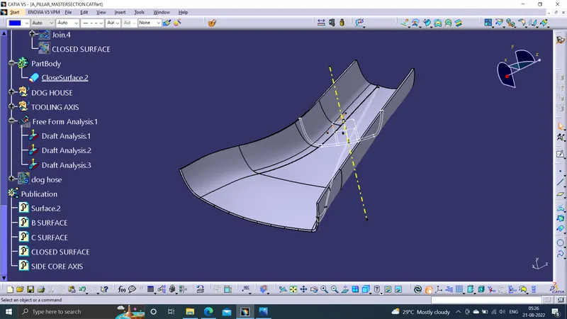
Join the Class A and Class C surfaces.Trim those joined surfaces with Class B surfaces.Go to Part Design and insert a Body and create a closed solid body from closed surface.
DRAFT ANALYSIS
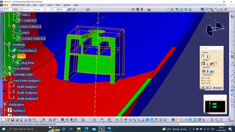
Go to the Insert menu and select the Analysis option.Select Feature Draft Analysis.Select the Material option and select the surface.Drag the compass and place on tooling axis.Make sure that the top surface is in green colour as draft angle should not exceed 3deg.Click on Okay after confirm the mod
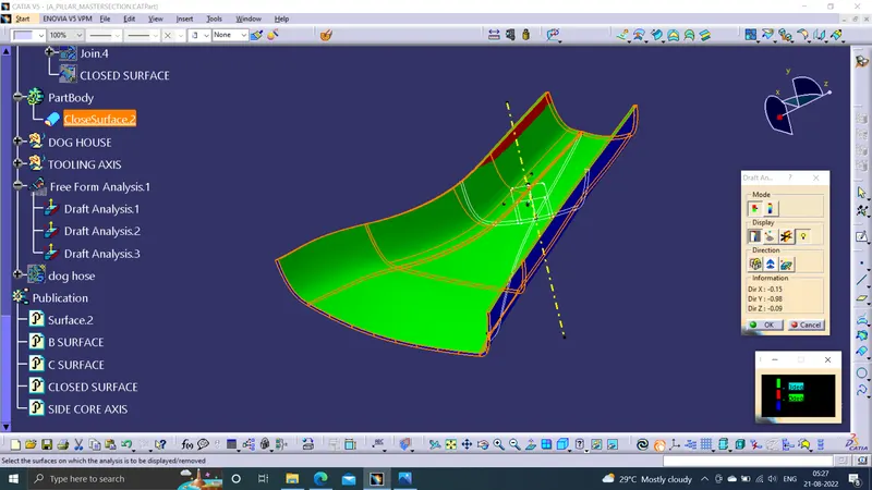
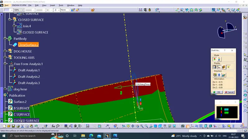
Minimum draft angle of a solid part is 2.06 degree.
Dog House creation:
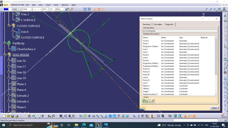
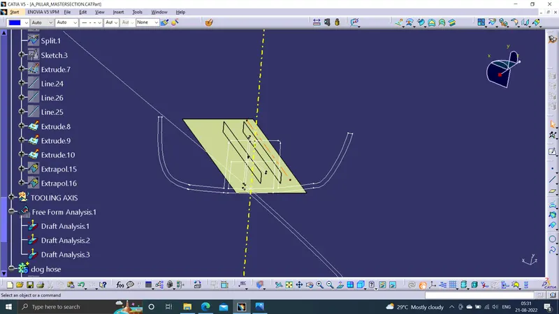
To create the dog house on the B-side, extracted the lines on the master section and create a plane to extract the lines concerning the master section. Extracted the faces which are required to create the shell for the dog house, and then trim the surfaces with each other as per the master section dimensions.
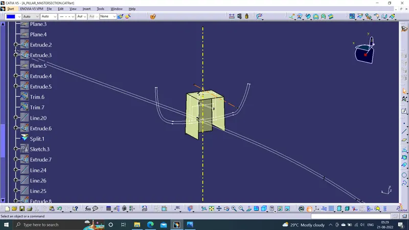
I created the side core access, by creating a line at the centre of the back surface by creating the point and then thicken the shell for mm to inside. After thickening the surface, I gave deg draft to inner surfaces of the dog house.
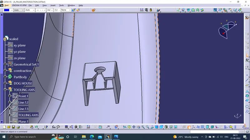
DRAFT ANALYSIS OF A DOGHOUSE
IMAGES OF A PILLER
i