Week 14 challenge
OBJECTIVE
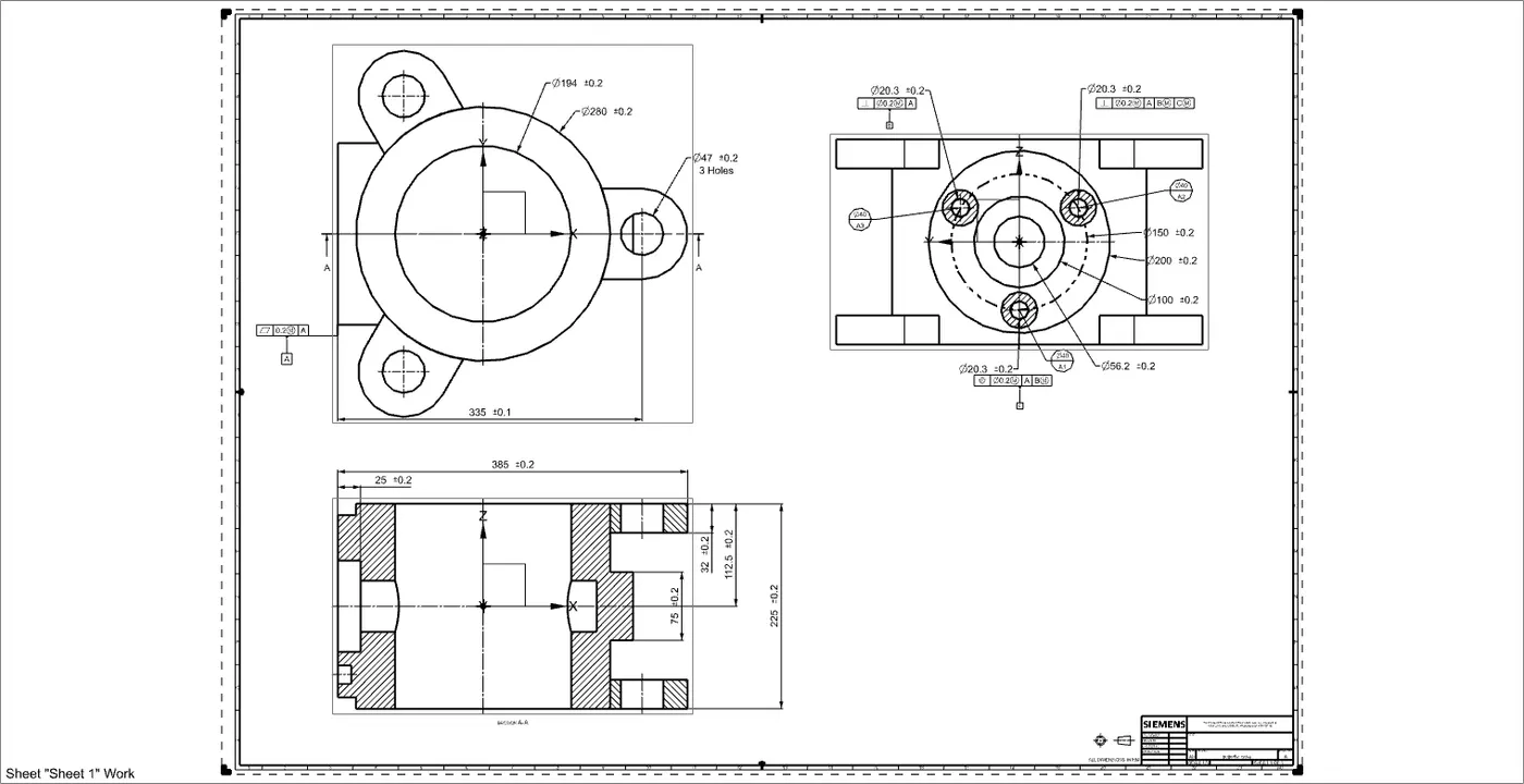
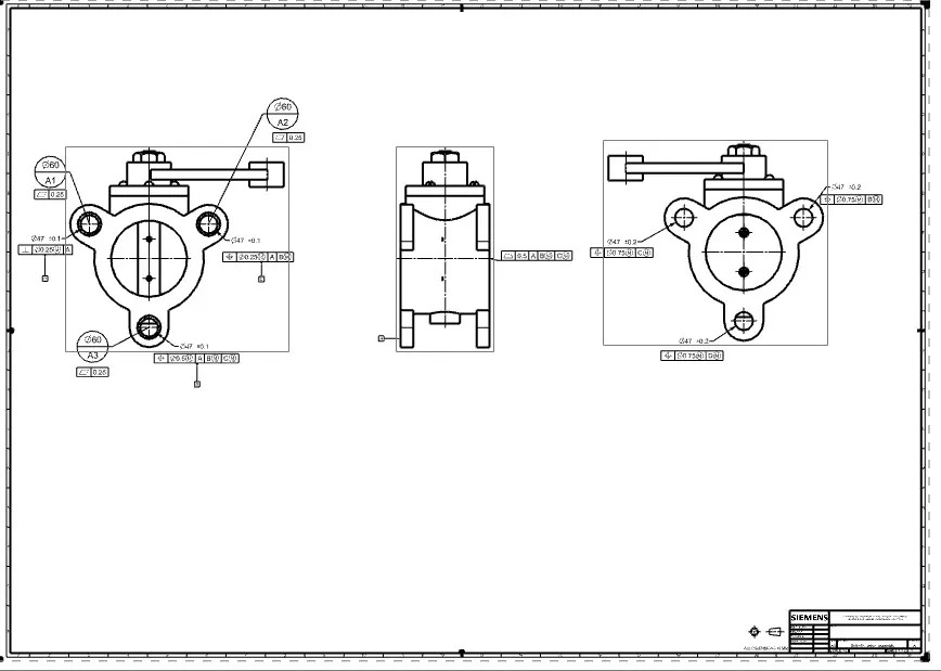
The objective of this project is to design a butterfly valve and apply GD&T to its components and final assembly using Siemens NX.
INTRODUCTION
GEOMETRIC DIMENSIONING & TOLERANCE
- Geometrical dimension is a geometric characteristic, the size of which is specified as length angle location or Centre of distance etc.
- Tolerance on a dimension is the total permissible variation in its size, which is equal to difference between the maximum and minimum size.
- GD&T is a symbolic language used in engineering drawing. It is a symbolic language used to specify size shape orientation and location on a part.
- It is used to control dimension variation in part. So less variation means less waste
- It is used for ensuring the proper assembly of mating parts.
BODY OF BUTTERFLY VALVE
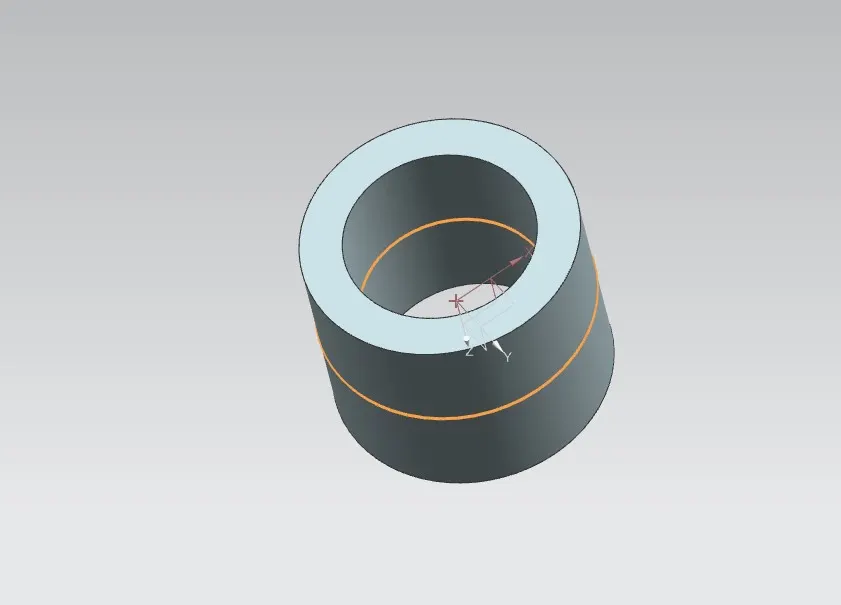
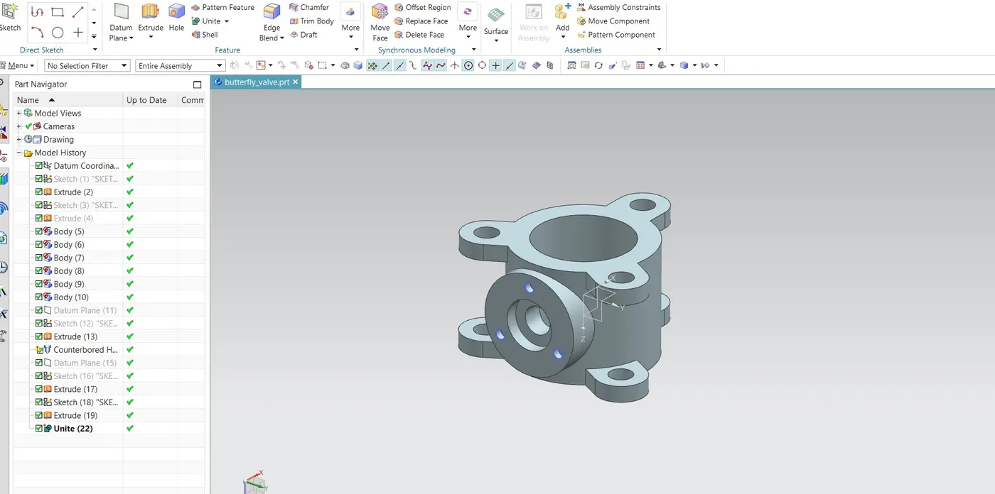
- Create two circles of the required diameter and use the Extrude command to form a cylindrical body.
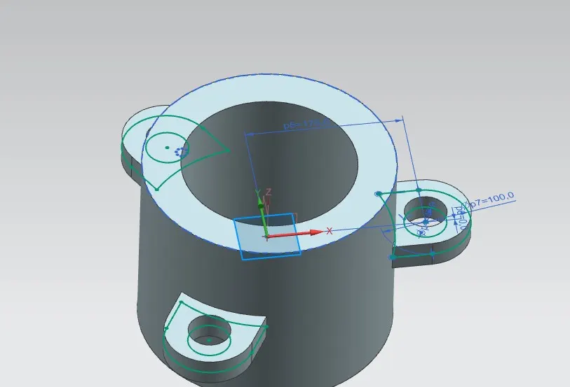
- On that cylindrical body create three lugs with holes in them. This will help us connect the butterfly valve to the pipe flanges. We have created the lugs on the mid-plane and then Extruded them with reference to the mid-plane(i.e. symmetrical value).
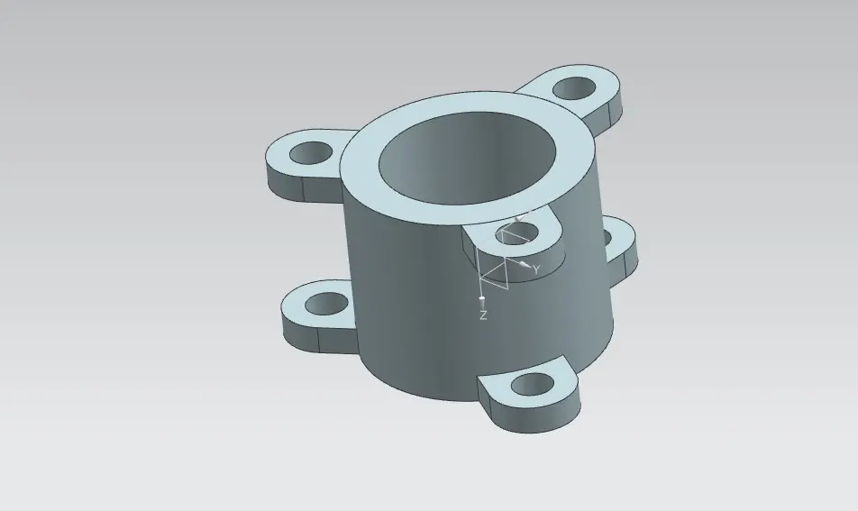
- Using the Move object command we created similar lugs on the outer surfaces of the body with the help of lugs created earlier.
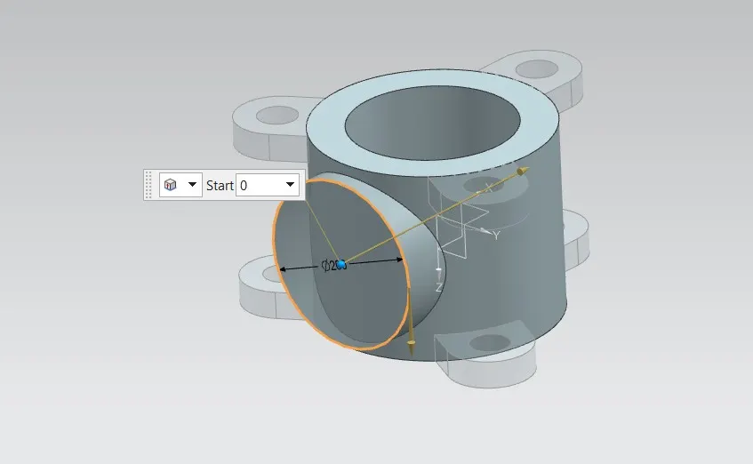
- Create a new datum plane and draw a circular sketch of the required diameter. Extrude this sketch up to the cylindrical body using the extrude command.
- Then create counterbored holes in the body using the Hole command so that we can insert shaft/stem in it. Specify all the required values of diameter and hole depth accordingly.
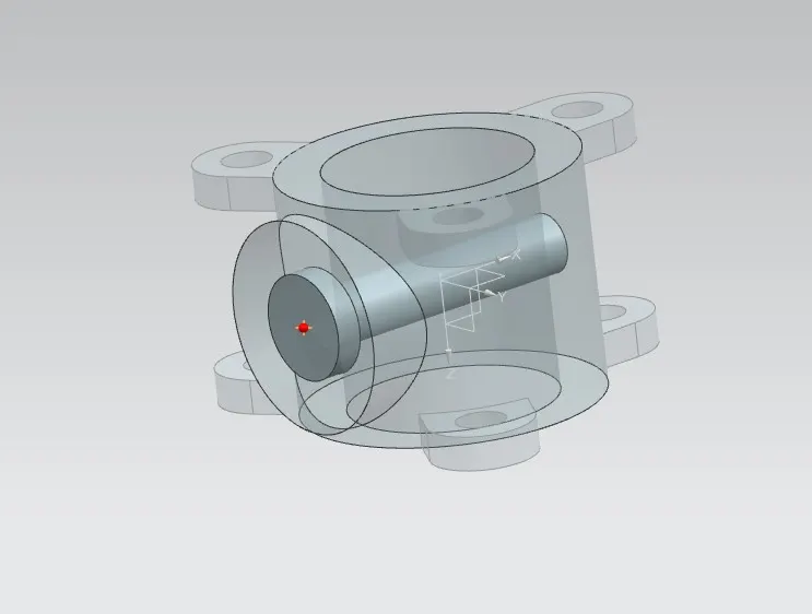
- Create another datum plane on the other side of this newly created feature. Develop a circular sketch on this new plane and then extrude it up to the cylindrical body.
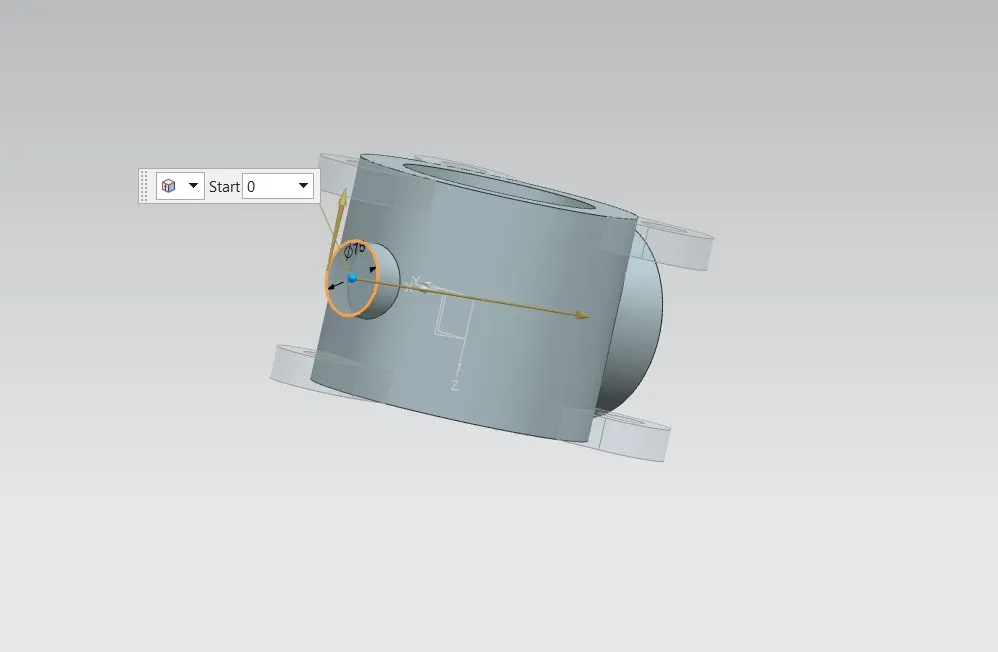
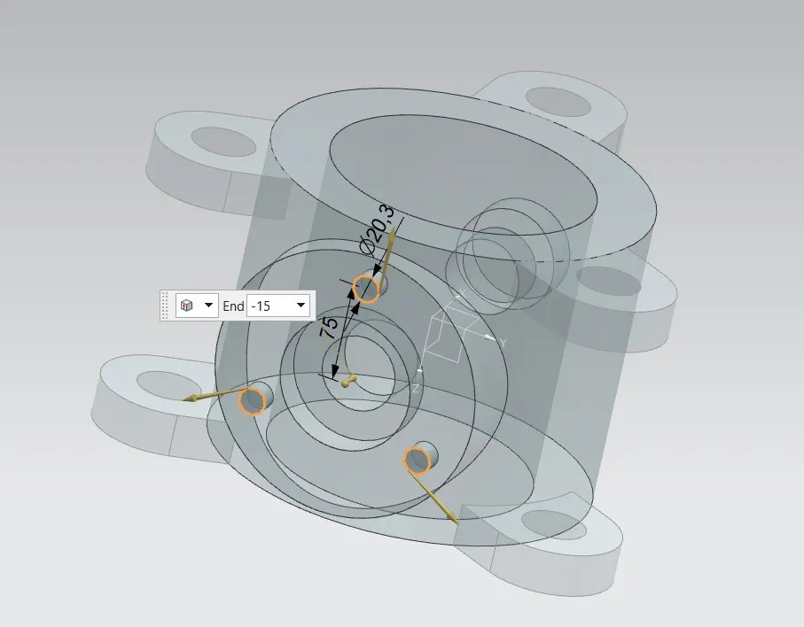
- On the outer surface of the parent feature of the counterbored hole, create three small holes using the extrude command so that we can assemble other components to the body.
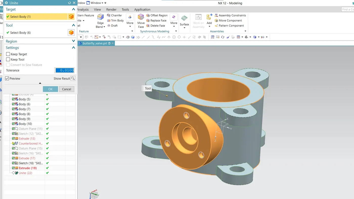
- Combine all the features to form a single object using the Unite command.
ISOMETRIC VIEW
DRAWING SHEET WITH GD&T:
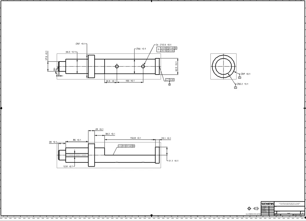
SHAFT OF BUTTERFLY VALVE
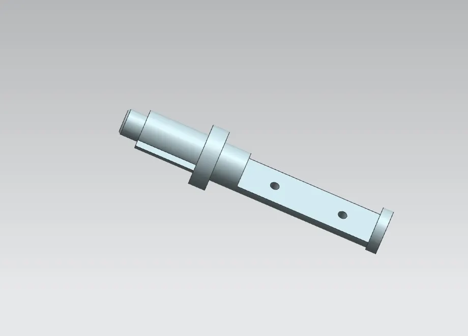
- The stem of the butterfly valve may be a one-piece shaft or a two-piece design. This design consists of a one-piece shaft. The disc/plate, lever, and nut are assembled into this shaft.
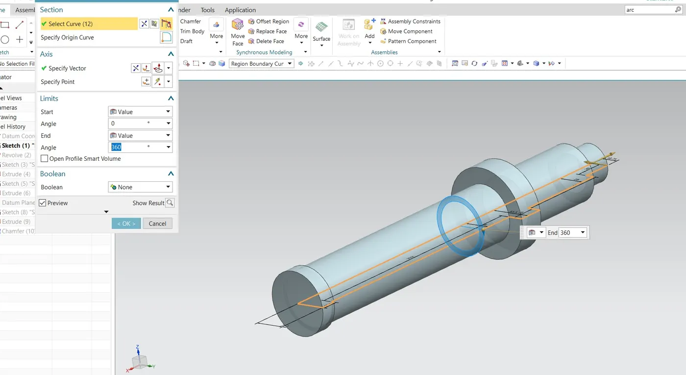
- First, create a sketch that is cylindrical along with steps. That sketch must be fully constrained and closed to use the Revolve command.
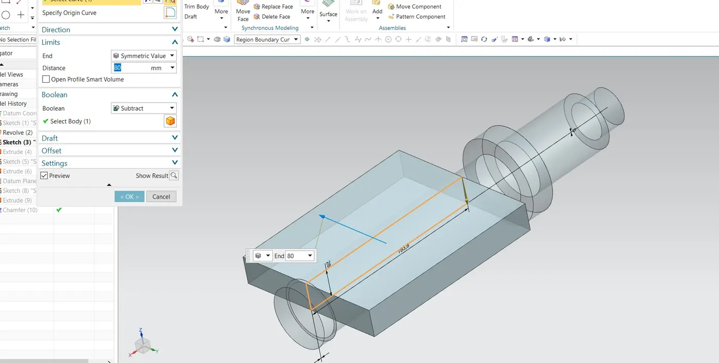
- After creating the main body we have to create two rectangular slots on it.
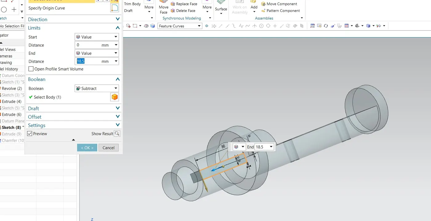
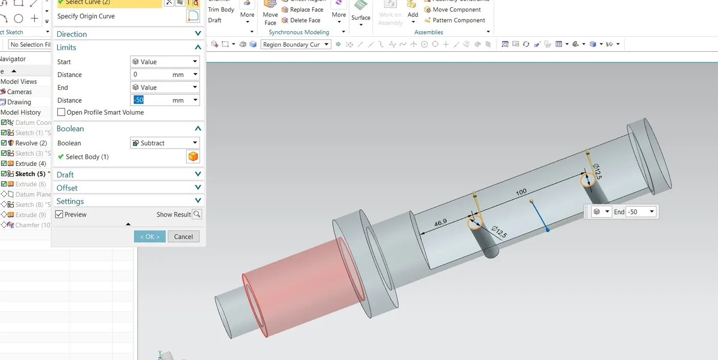
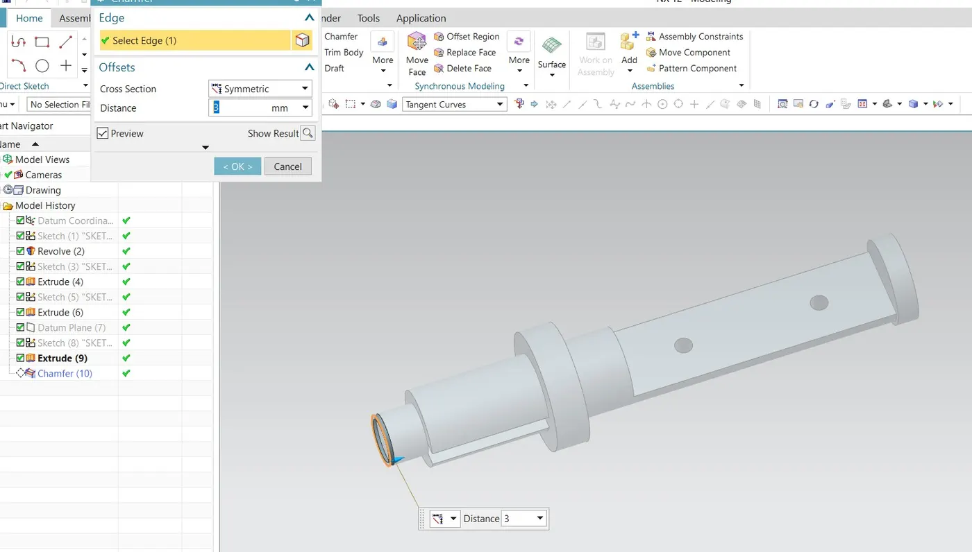
- Then create two holes on the face of the bigger slot where the disc/plate will be attached. Then provide a chamfer on the front circular edge for better handling and safety reasons.
MODEL VIEW
DRAWING SHEET
RETAINER OF BUTTERFLY VALVE
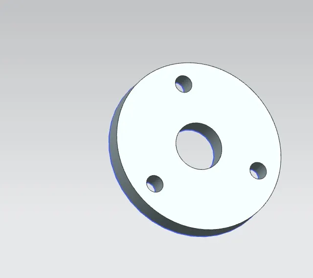
- Retainer is nothing but a kind of washer assembled on the body of the butterfly valve.
- Create a circular sketch with an appropriate diameter. Also, create 3 holes in the sketch that will help us to fix the retainer to the body of the butterfly valve.
DRAWING SHEET
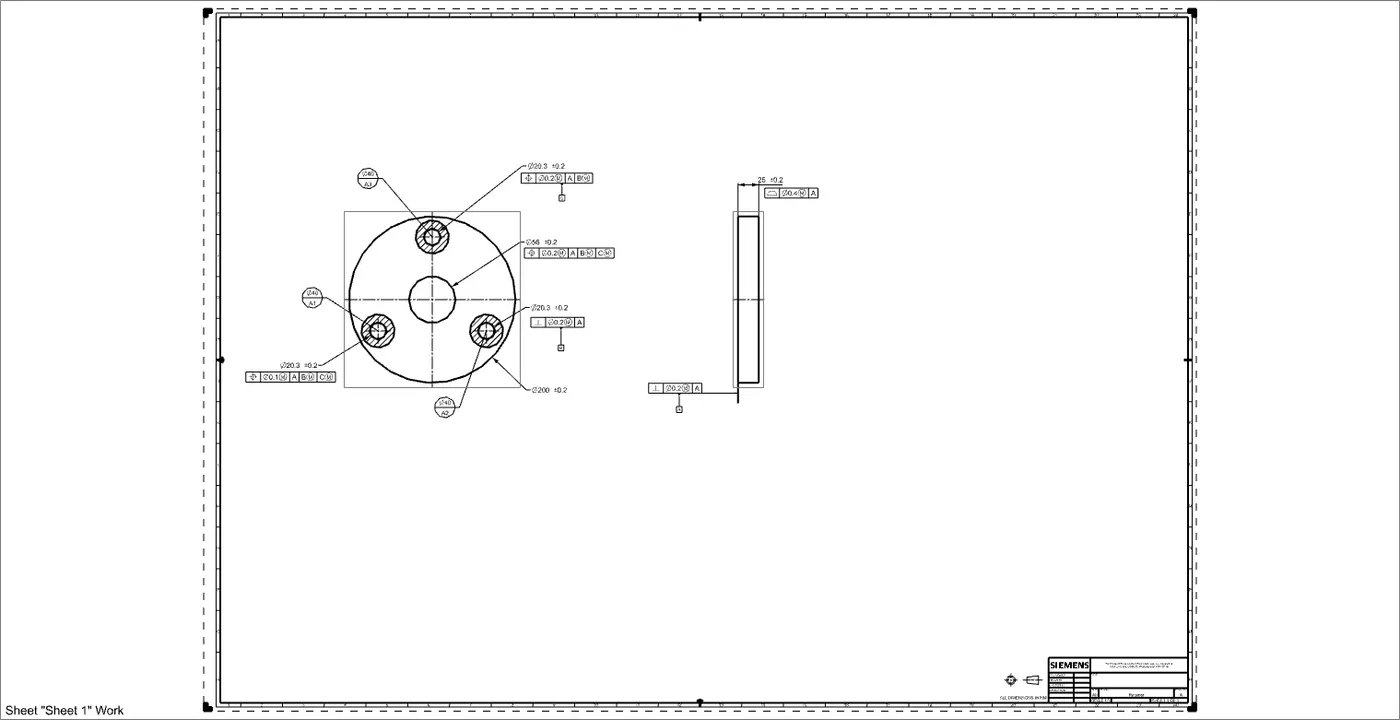
PLATE OF BUTTERFLY VALVE
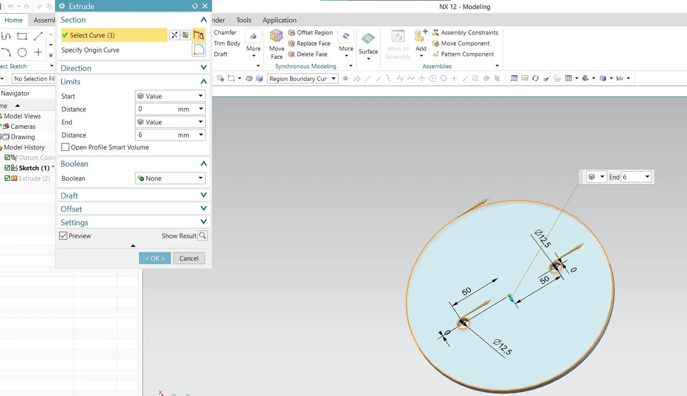
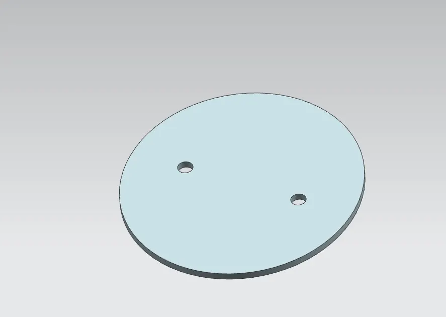
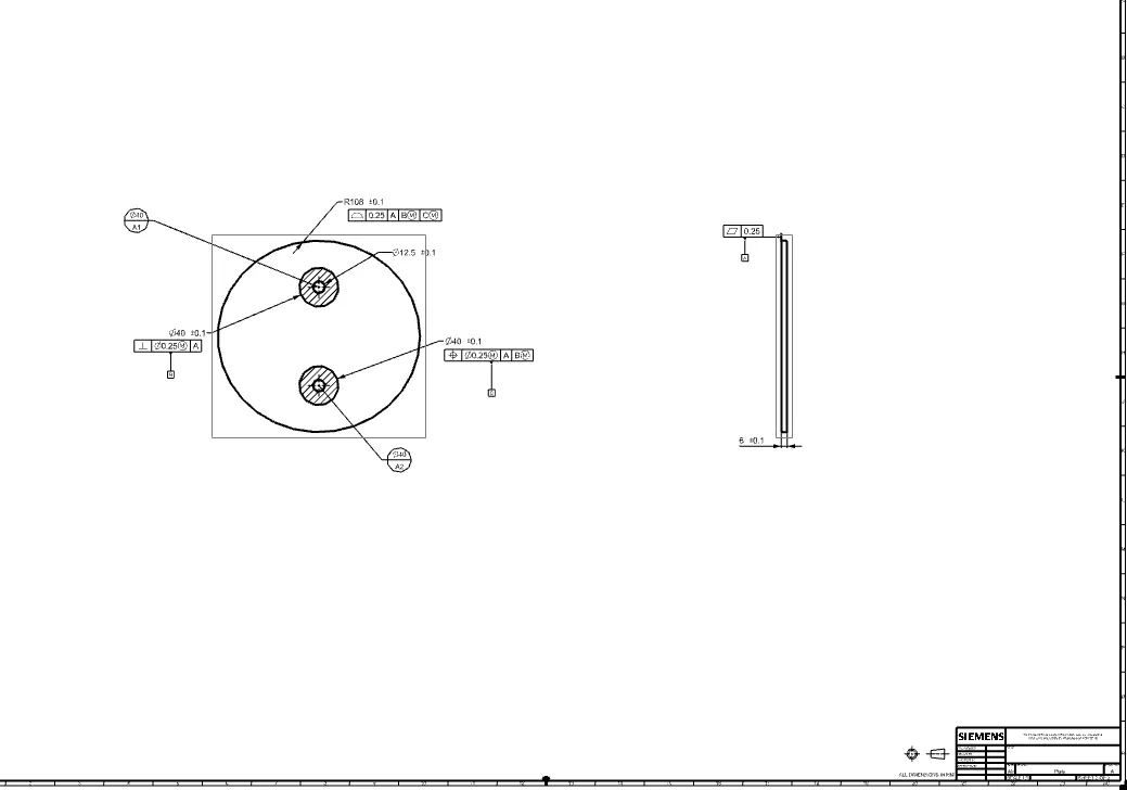
- A disc is nothing but a flow-controlling/closure member of the butterfly valve which is attached to the stem/shaft. The disk is the equivalent of a plug in a plug valve, a gate in a gate valve, or a ball in a ball valve.
- Create an elliptical sketch with appropriate sizes (major & minor distance). Then put two holes along the minor axis which will be used to fix the disc to the shaft.
- Extrude the fully constrained sketch by providing suitable thickness.
MODEL VIEW
DRAWING SHEET
LEVER HANDLE OF BUTTERFLY VALVE
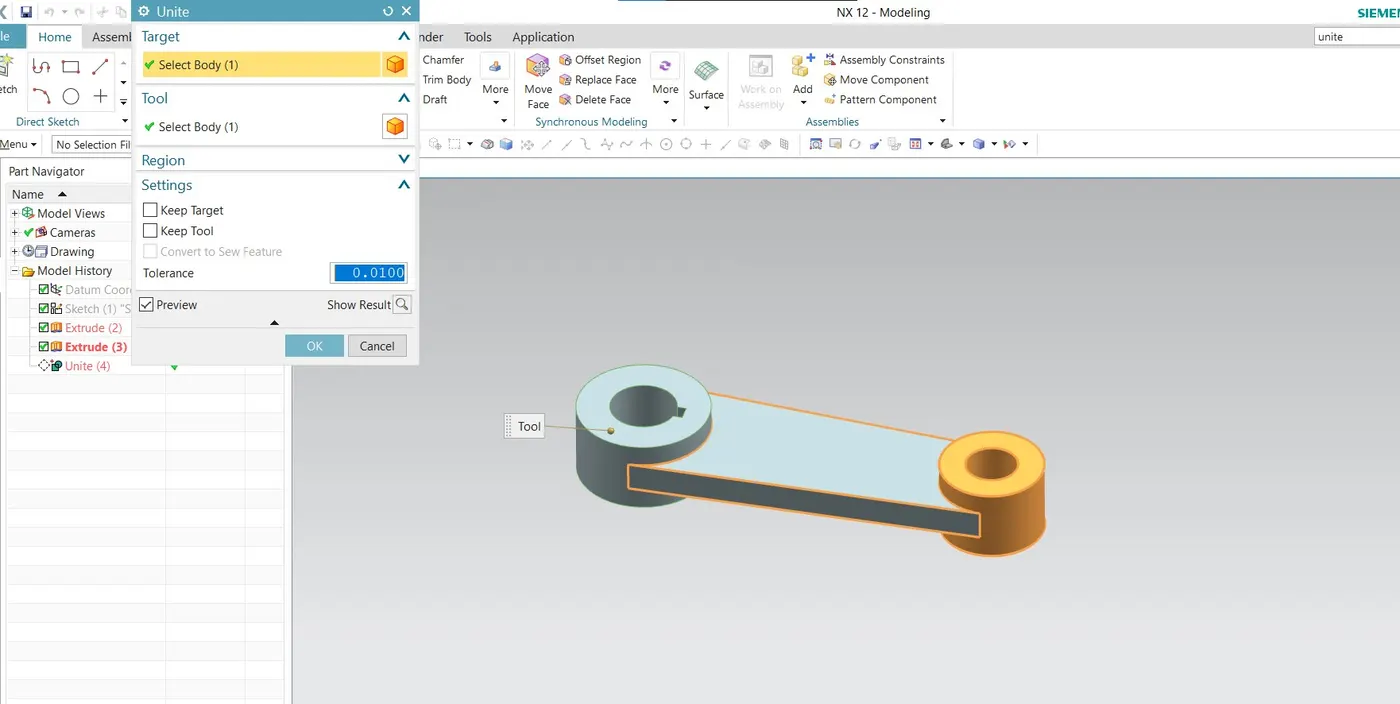
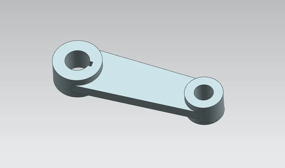
- Create two circular sketches with the appropriate diameters, and specify a suitable distance between them. Also, create a keyway slot in the bigger diameter sketch. Join these two sketches with a line tangent to both the circles.
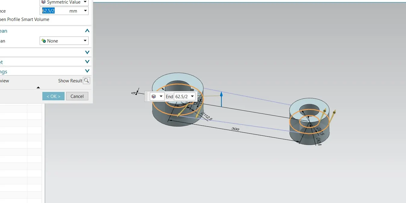
- After creating the fully constrained sketch, first, extrude the circular regions and then extrude the mid-section with different thickness values.
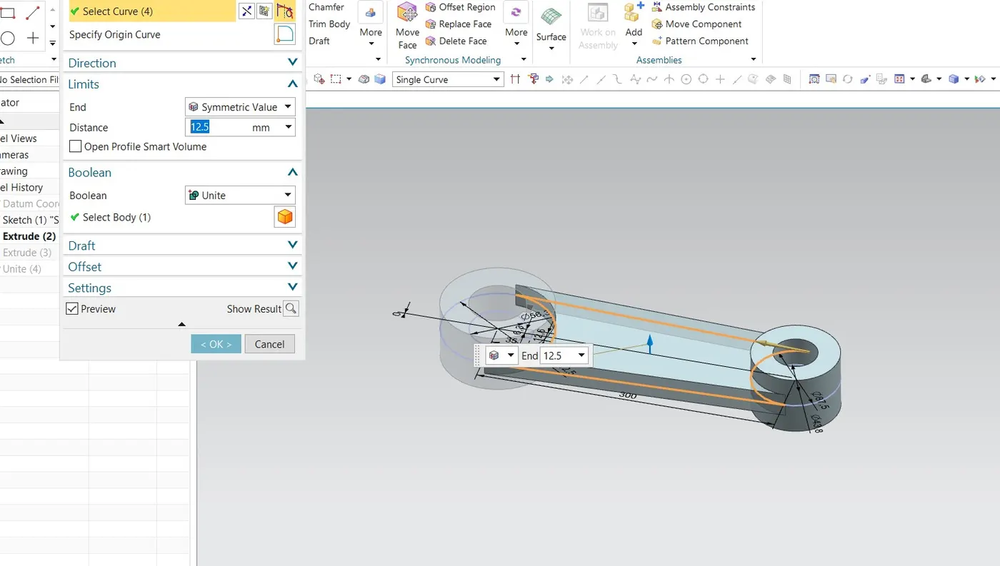
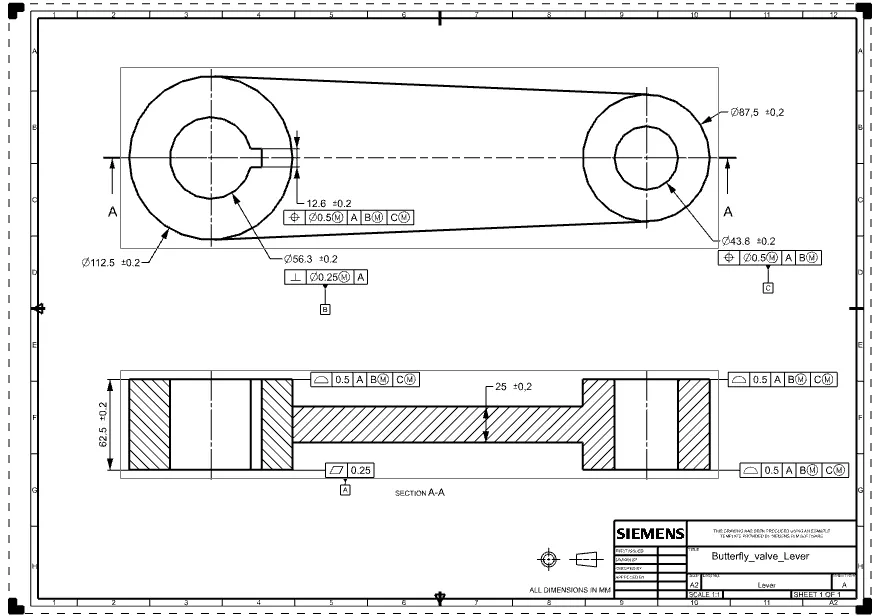
- Then combine all the features using the Unite command. Then create a drawing sheet of the model and apply GD&T to the drawing.
MODEL VIEW
DRAWING SHEET
NUT - BUTTERFLY VALVE
- Nut is used to keep the lever and retainer intact with each other as well as the body of the butterfly valve.
- Create a polygon sketch (6sides) with suitable dimensions. Also, add a circular hole in the sketch so that it can be inserted into the shaft.
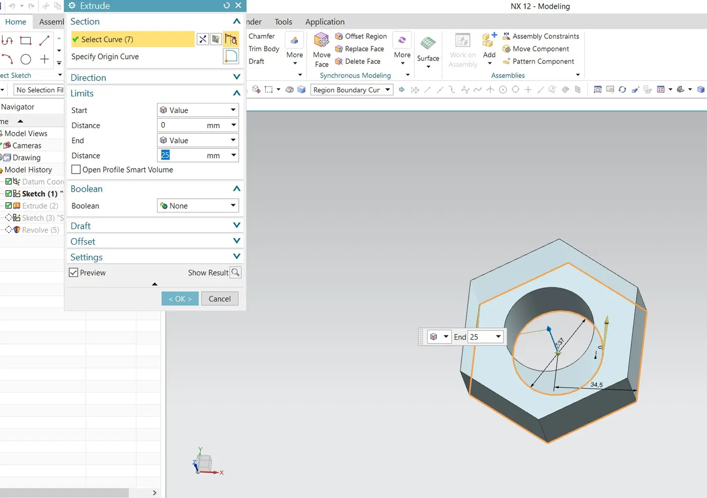
- For safety handling provide a fillet on the top edge of the nut.
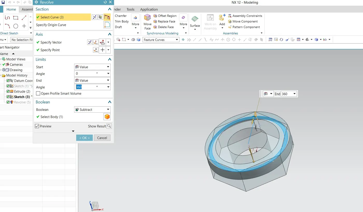
MODEL VIEW
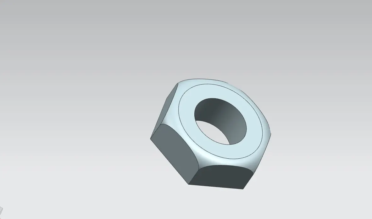
DRAWING SHEET
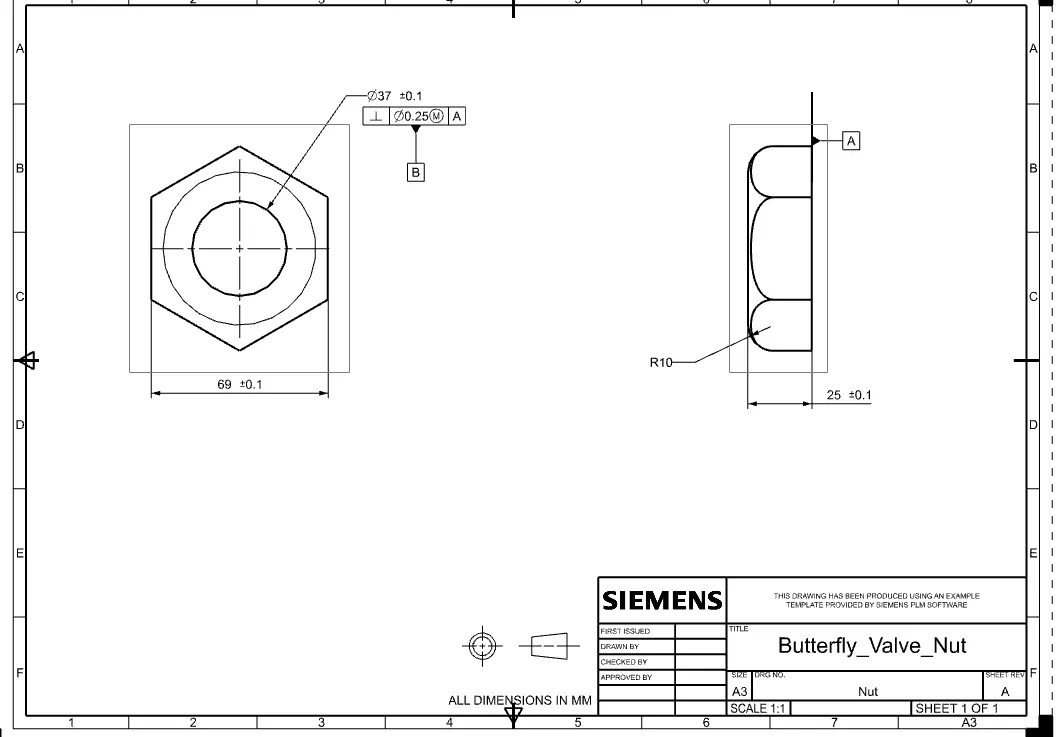
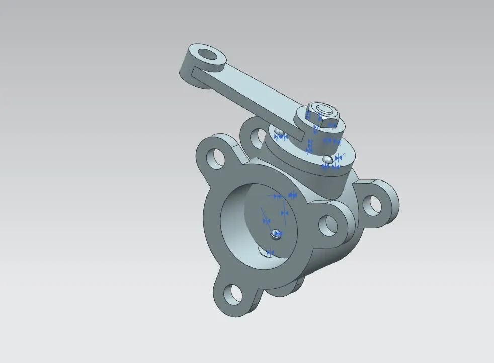
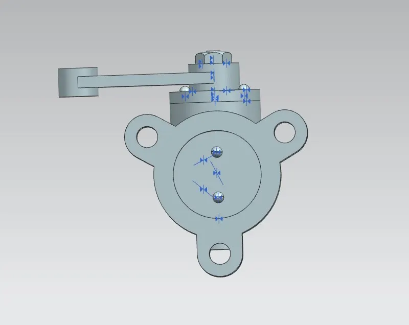
BUTTERFLY VALVE ASSEMBLY:
MODEL VIEW
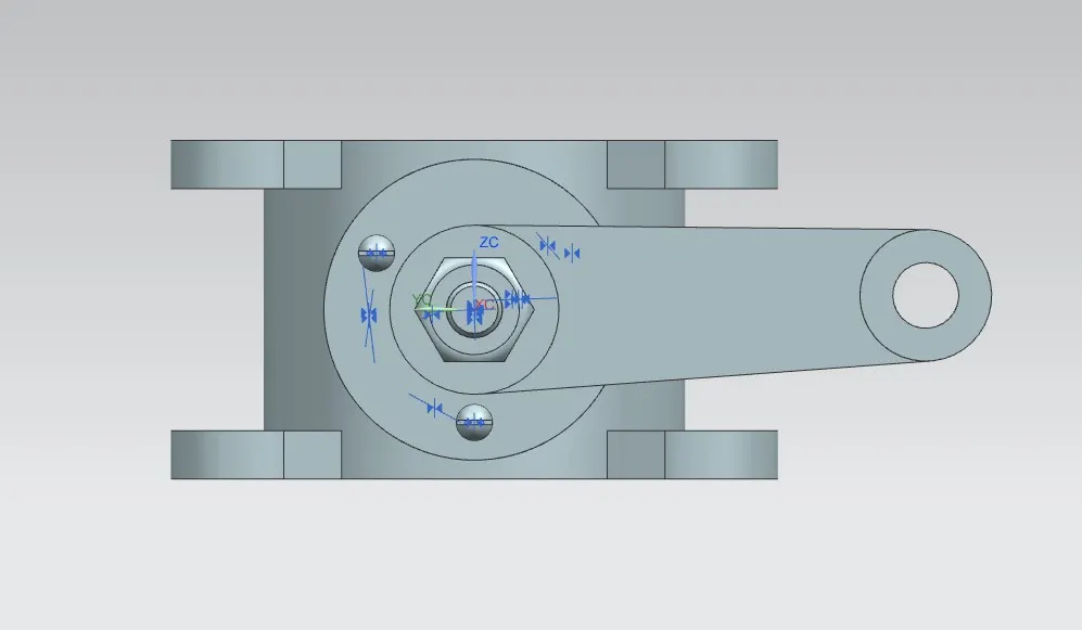
DRAWING SHEET WITH GD&T
CONCLUSION
- Butterfly valve was successfully designed using NX cad and GD&T applied to all parts and the assembly of the Butterfly valve.