Week 9 - Attachment Feature Creation (Ribs & Screw Boss) - Challenge 1
DRILL HANDLE DESIGN WITH RIBS AND SCREW BOSS
AIM: Create the rib and Create the Screw boss for the Drill Handle considering the design rules.
OPERATION
CLASS A SURFACE
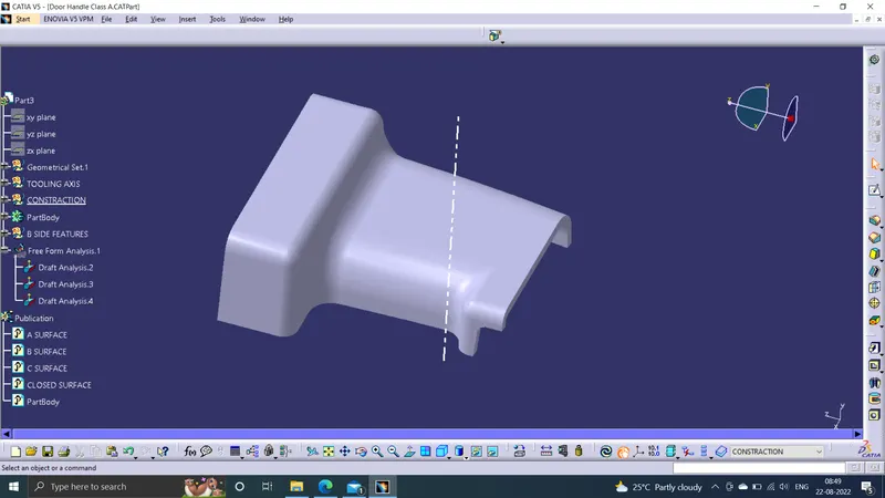
We get class A surface as a input. we create B surface and C surface using this class as a refference.
TOOLING AXIS
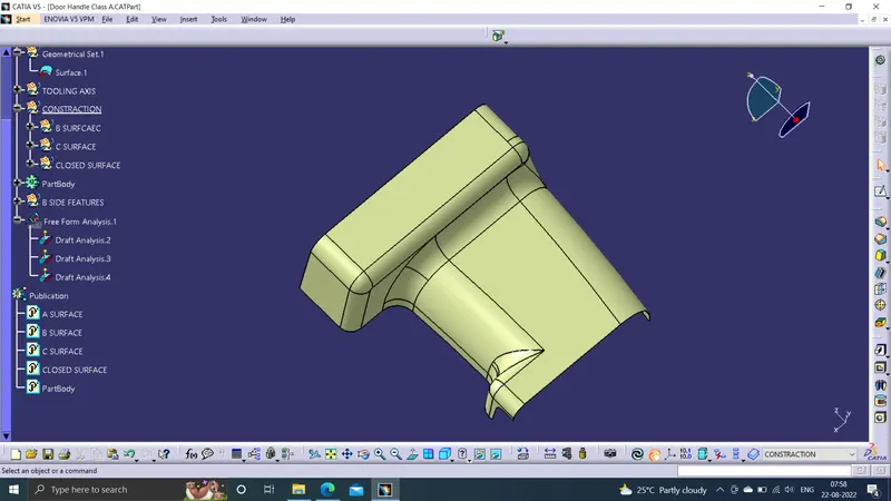
To create the tooling axis, I extracted a surface from class A and created a point in the middle of the surface by using the point command and created a line at that point through the x-axis. Now, I performed a draft analysis check from that line whether the created tooling axis is in the correct position or not. If, in the draft analysis check the surface highlighted with green colour on both sides of the surface the tooling axis is in the correct position and direction.
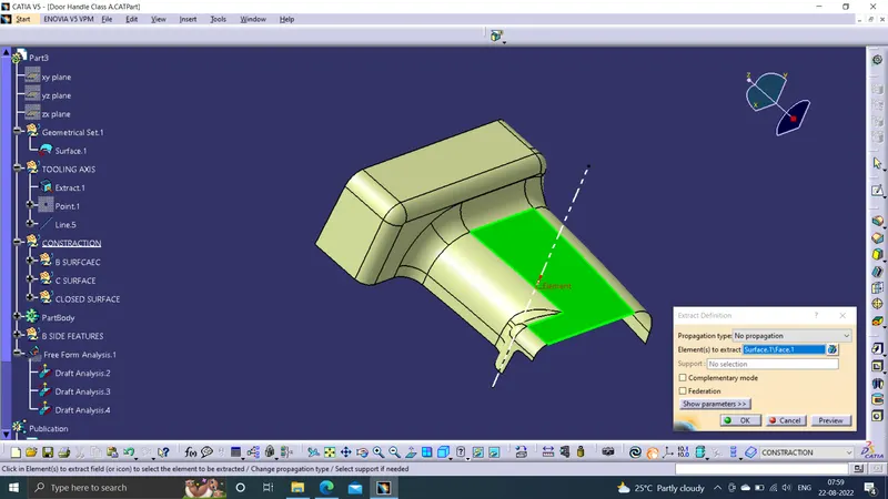
DRAFT ANALYSIS OF CLASS A
Now, I performed a draft analysis check from that line whether the created tooling axis is in the correct position or not. If, in the draft analysis check the surface highlighted with green colour on both sides of the surface the tooling axis is in the correct position and direction. 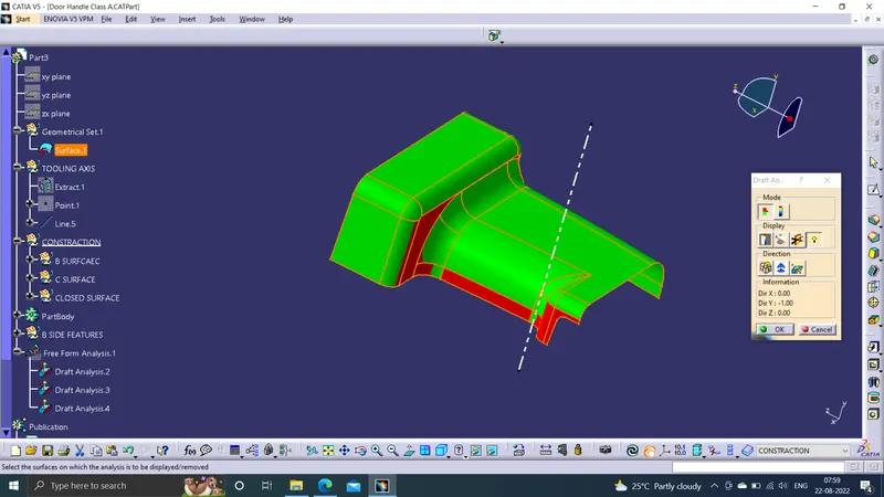
But we can see some part of class A has less than 1 degree draft. class A team need to change these areas to overcome the manufacturing deffects.
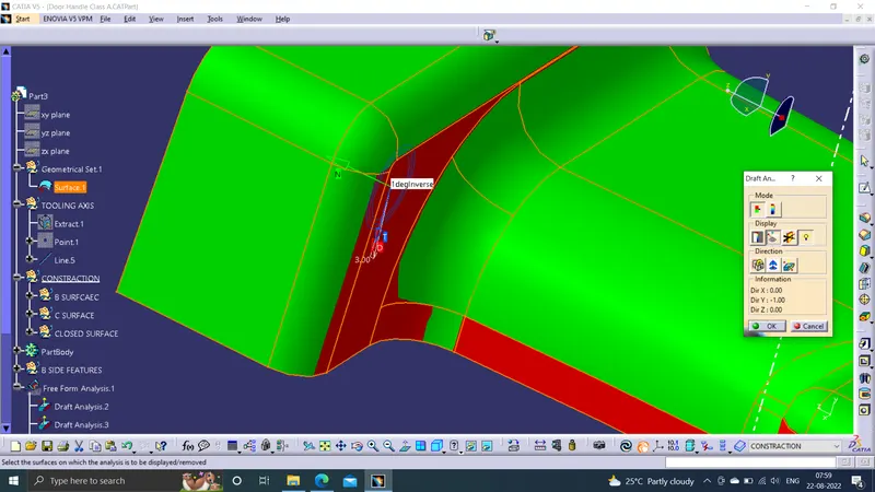
B SURFACE CREATION
To create the class B surface, offset the class A surface inside by 2.5mm thickness. Once the offset is created, we can observe a patche on the offset surface, those patche are formed due to the fillets on the class A surface. We need to fill those patche with the help of the multi-section surfaces or sweep commands by extracting the patch boundaries. Once the patche on the offset are covered properly join all the patche with the offset surface, to get the replicated surface of the class A surface.
Patche to be filled
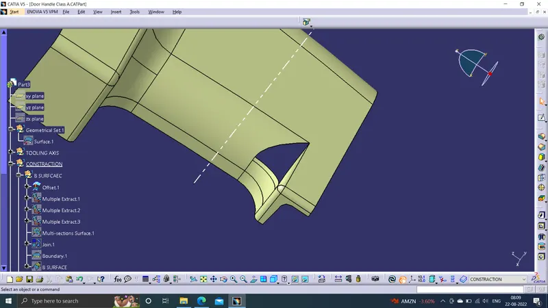
Filled patche
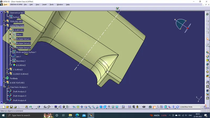
C SURFACE CREATION
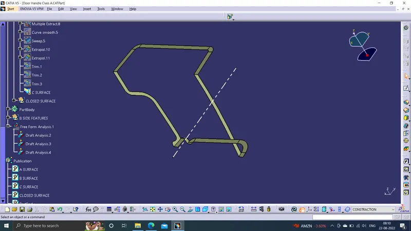
Get the boundary lines of Class A surface separately.Smooth the curves with a smooth option as boundary lines have a lot of vertices.Sweep the curves with tooling axis as direction in Sweep option.As both lines do not intersect, extrapolate them with a certain distance.Trim the surfaces.
CLOSED SURFACE
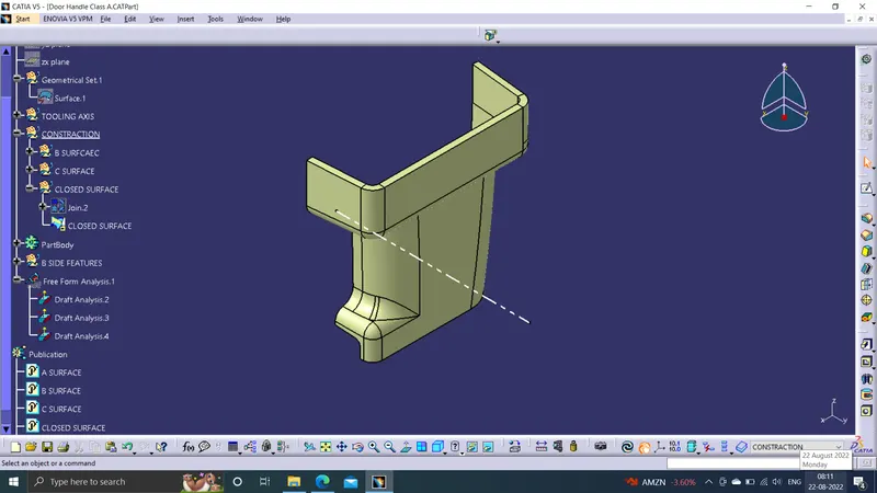
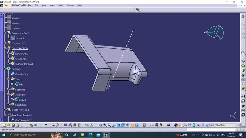
Join the Class A and Class C surfaces.Trim those joined surfaces with Class B surfaces.Go to Part Design and insert a Body and create a closed solid body from closed surface.
DRAFT ANALYSIS
Go to the Insert menu and select the Analysis option.Select Feature Draft Analysis.Select the Material option and select the surface.Drag the compass and place on tooling axis.Make sure that the top surface is in green colour as draft angle should not exceed 3deg.Click on Okay after confirm the model.
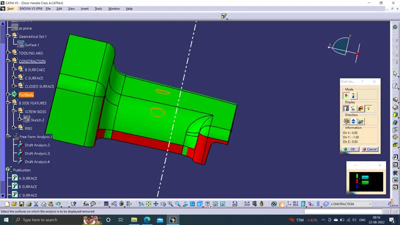
Because of the problem in Class A we get less than 1 degree draft on part body.
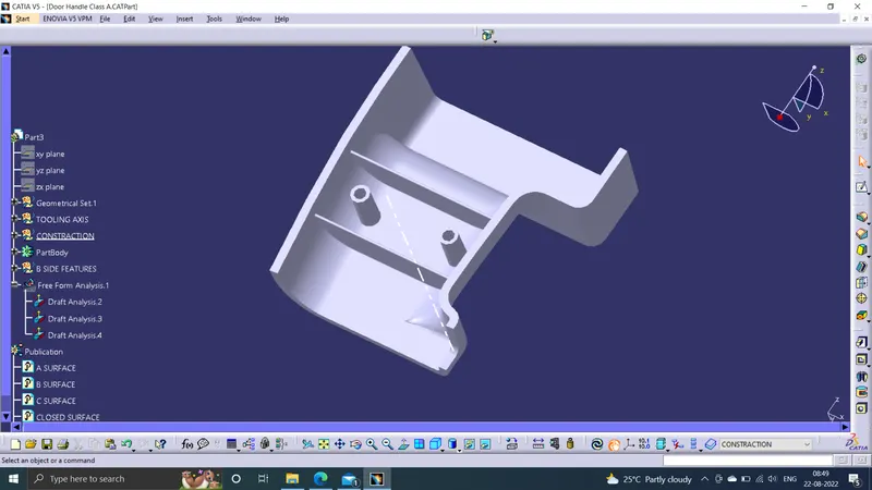
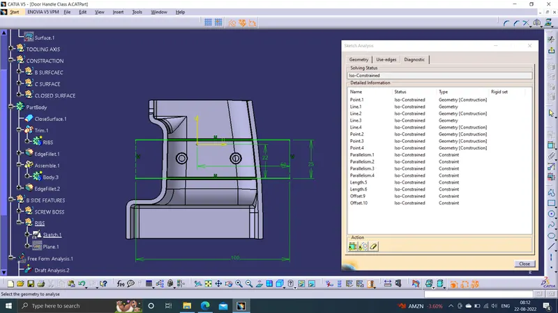
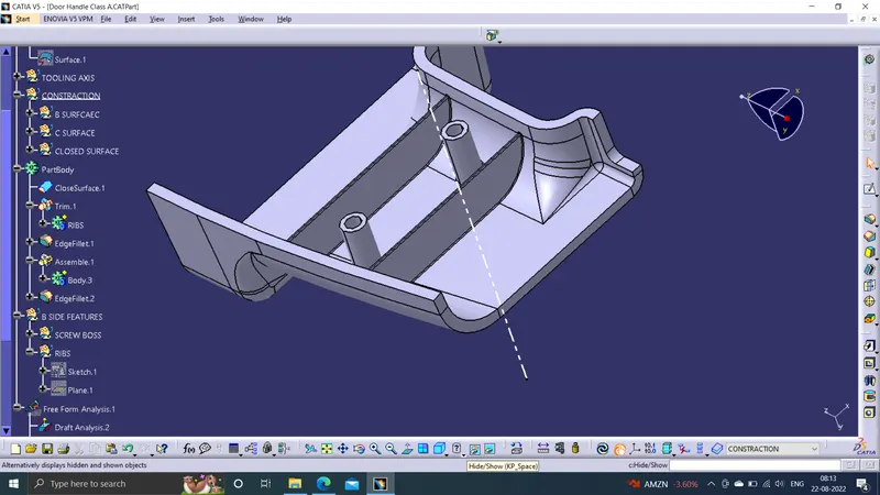
RIBS :Therefore Ribs are used in plastic parts to increase bending stiffness without increasing plastic part thickness.
SCREW BOSS
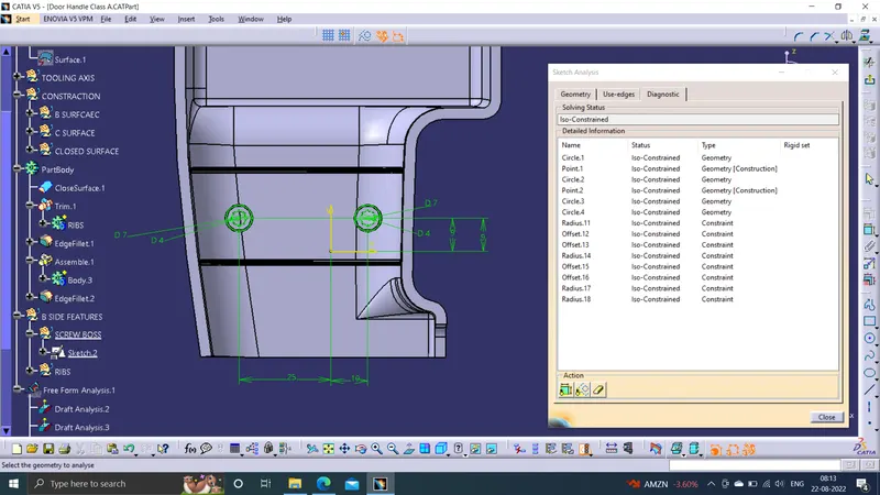
General Guidelines for Bosses:
- Draft - 0.5 degrees on the walls of boss
- Thickness - Typically 40%* of the nominal wall at the base.
- Height to Diameter Ratio - 3:1
- Radii - 0.25mm maximum radii.
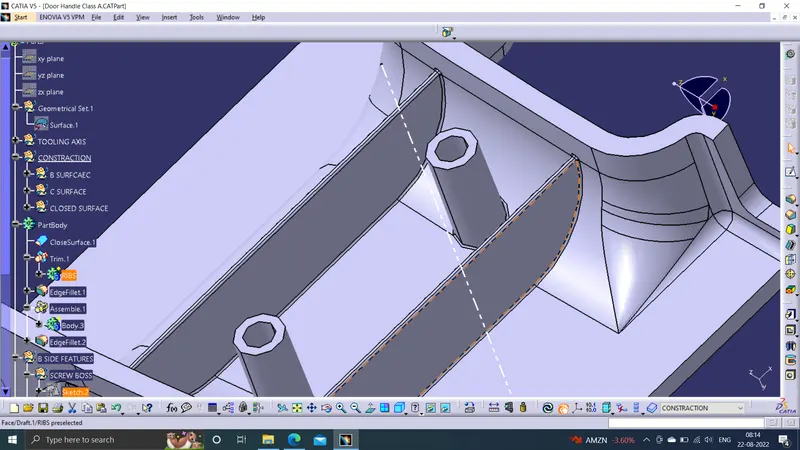
DRAFT ANALYSISIF RIBS AND SCREW BOSS
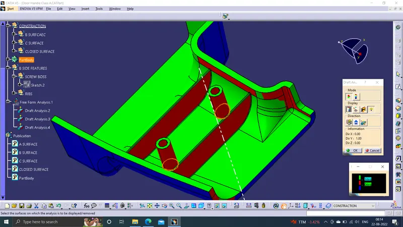
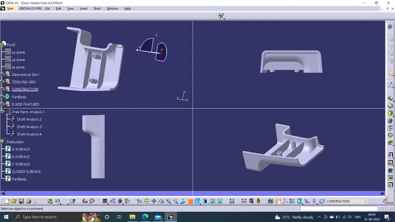
DOOR HANDLE IMAGES