Week 9 - Project 1 - Door Applique Design with Engineering Features
DOOR APLIQUE DESIGN WITH LOACATORS AND HEAT STAKES
HEAT STAKES
The Heat Stakes are neccessary to join a Thermoplastic tp part of a disimilar metal, whwether it be a metal, dismilar plastic as other material.
General Description
- It is an assembly method that uses the controlled melting and referencing of a plastic stud or boss to capture another plastic component in assembly.
- The Plastic stud protudes through the hole in the component to lock in a place.
- The heated thermal tip contact the top of stud, which melts and fills the volume of the tip cavity to lock the component in place.
Advantages
- Simplification of Machinery.
- Reduce cost of Machinery.
- Multiple Fastening points.
DESIGN OF LOACTORS IN DOOR PANEL
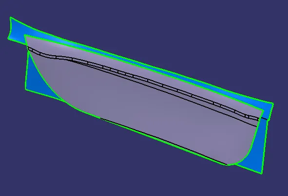
This is the given Door Applique Class A model and Door panel.
DRAFT ANALYSIS ON CLASS A
TOOLING AXIS AND DRAFT ANALAYSIS
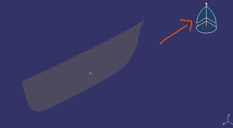
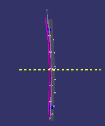
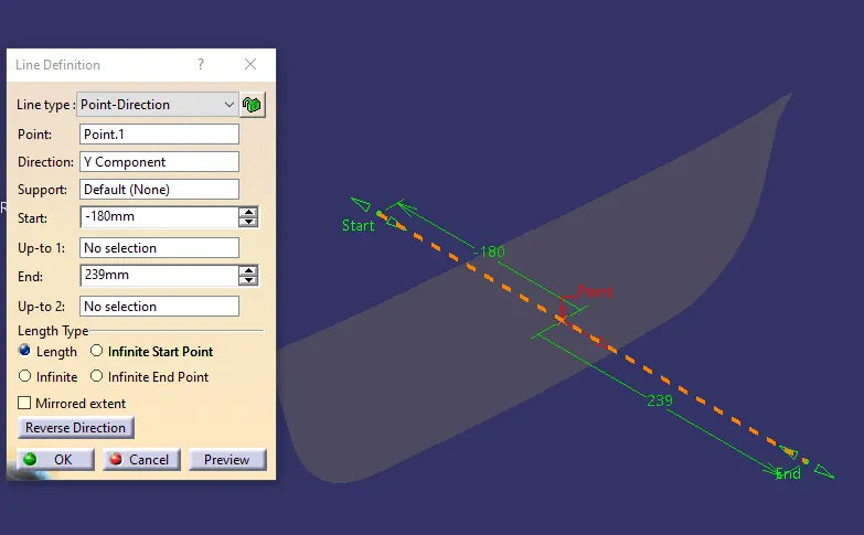
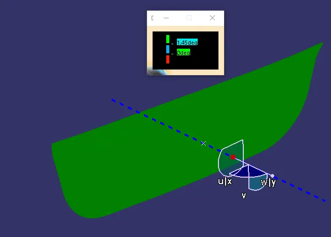
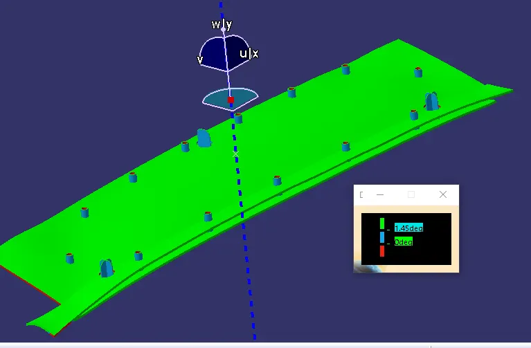
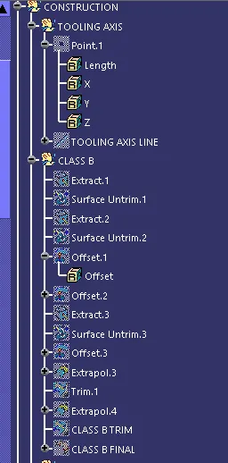
With the use above picture it clearly shows that tooling axis towards Y direction would clear all the faces . Create a point on a surfae with distance value of 0mm. With the point as a reference draw a line to a direction of Y axis and make it as an main tooling axis.
CLASS B SURFACE
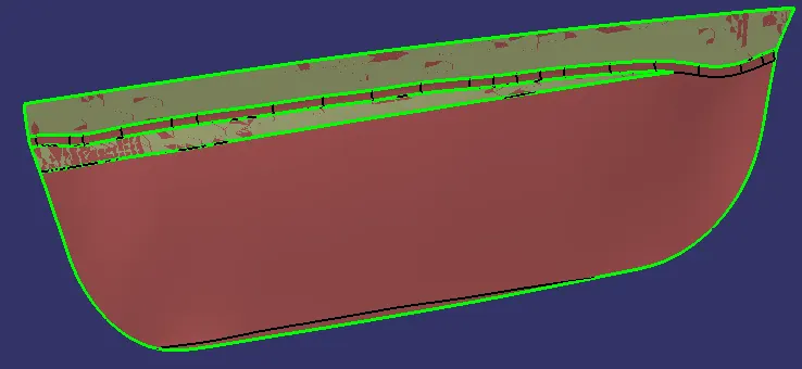
Extract the top 2 surfaces of the Class A make them as untrim and trim the both surface.
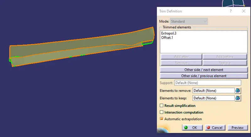
Extract the downward part , extrapolate them and trim with the top cleared trim surface to complete the Class B.
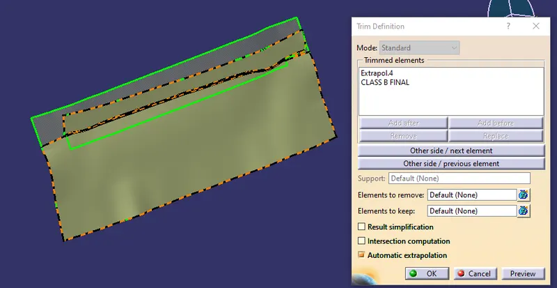
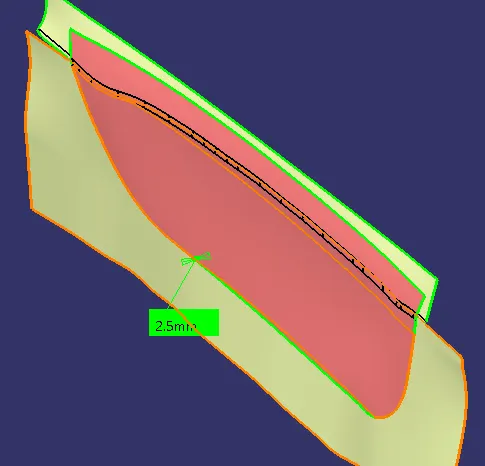
All the extrapolated parts should have an offset of 2.5mm behind Class A.
CLASS C SURFACE
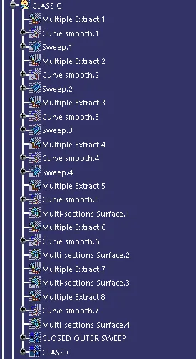
Extrude the Class A boundary convert the all extruded boundary lines to a smooth curve and apply sweep feature.
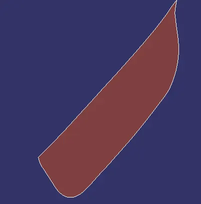

Join the both sweeped surface and Class A to complete a Class c surface.
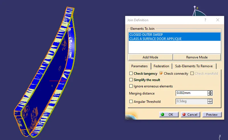

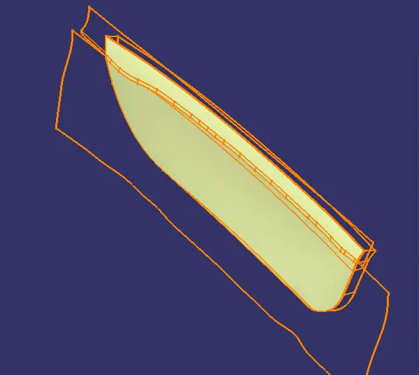
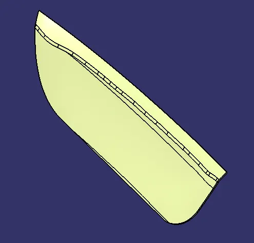
FINAL DOOR APPLIQUE CLOSED SURFACE
LOCATORS
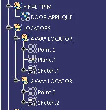
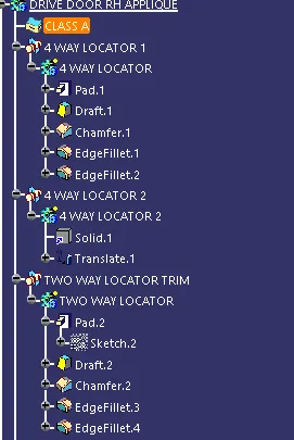
Before creating a Heat stake , we need locators to place the both component. It needs two 4 way locator and one 2 way locator followed by designs of Heat Stakes.
* 4 Way Locator
Refrence point has to be created with point on Door attachment surface with 0mm of distance, then create an zx plane parralel to the surface.Create a sketch at a random area some where left side top corner and constarined them with dimensions.
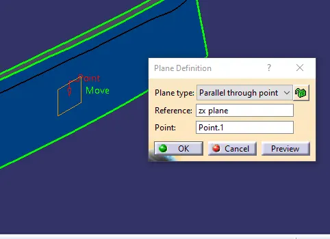
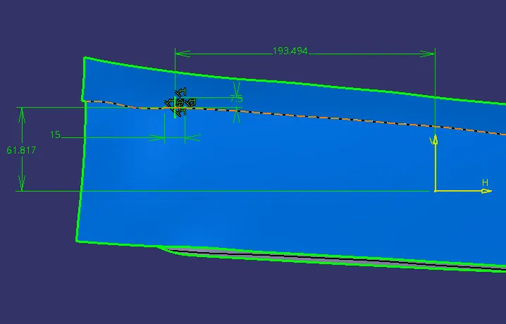
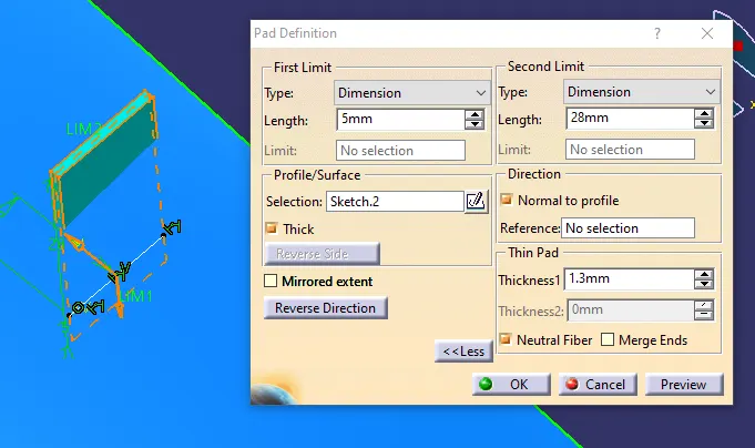
Insert a Body to Padup the sketch thicken the component as 1.3mm, as per the design rules followed in the Rib. Height of the locator should extend beyond the Door attachment.
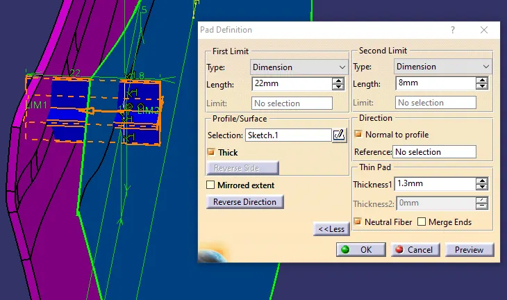
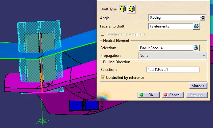
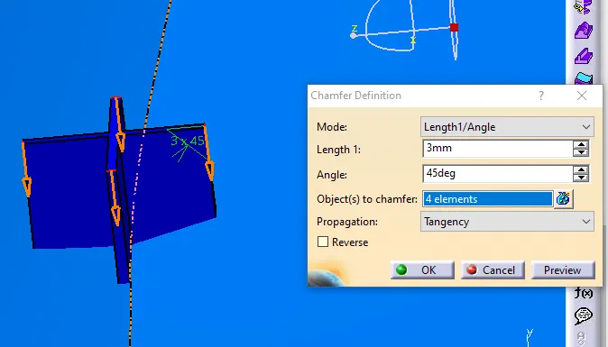
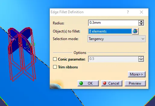
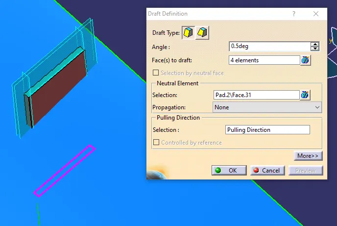
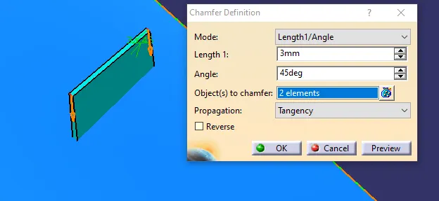
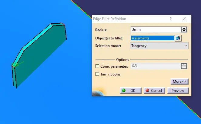
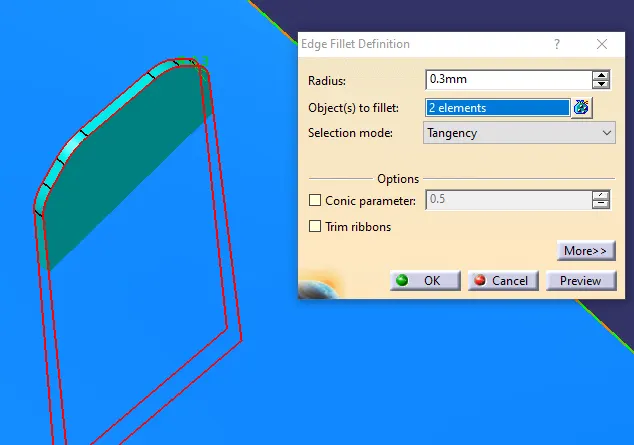
Apply draft angle,chamfer and fillet radius to the 4 way locator same design structure used in Ribs .
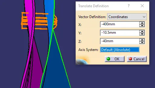
Translate the created 4 way locator to the right top corner with the coordinates of X,Y & Z.
Design of an 2 Way Locator
The two way locator is created to the center of the door surface at bottom side. Create a random point on a surface straight down to the previous created point and place the positioned sketch for a 2 way locator.
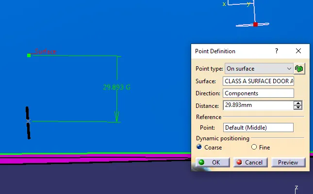
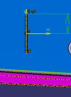
Insert a Body to padup the sketch of 1.3mm thickness , extend the length beyond the door surface. Apply the requiered draft angle chamfer and fillet radius same as given in 4 way locator.
Make the door reference surface has a solid with a thickness of 2mm, to assemble the locators and heat stake.
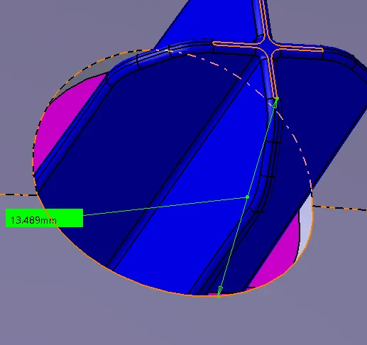
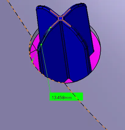
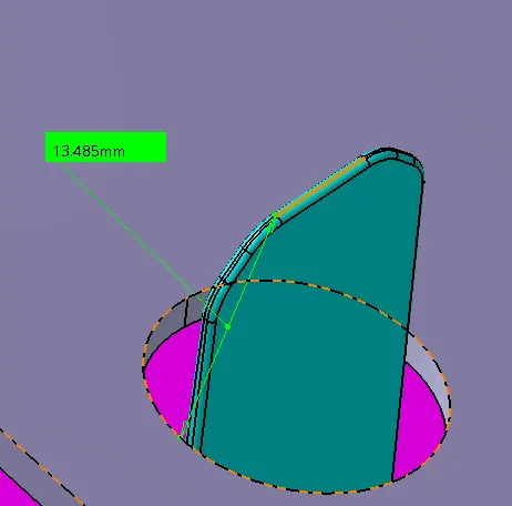
Check the height of the 4way locators and 2 way locators have same height with door panel surface as a refence.
DESIGN OF HEAT STAKE
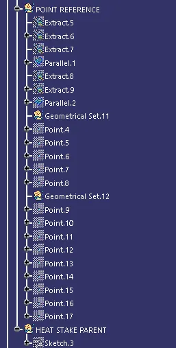
With the completion of the 4 way and 2 way locator, next up is Design of Heat Stake. Before designing a Heat stake we need a refrence points all over the boundary lines.
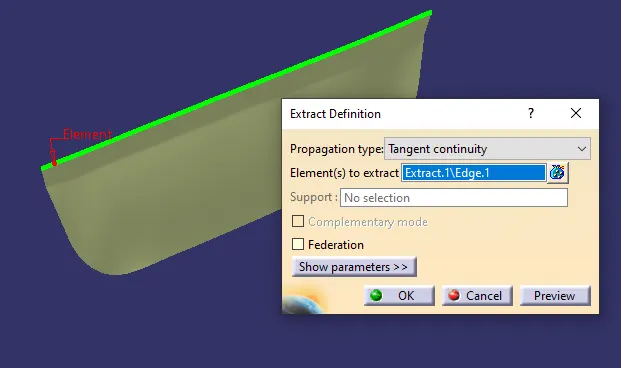
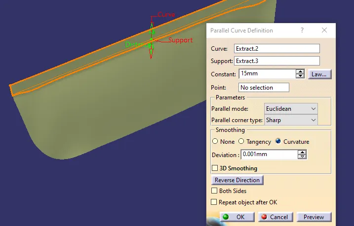
- Extract the class A surface and extract the boundary lines later using the parallel curve offset the boundary inside the part to create a refrence points.
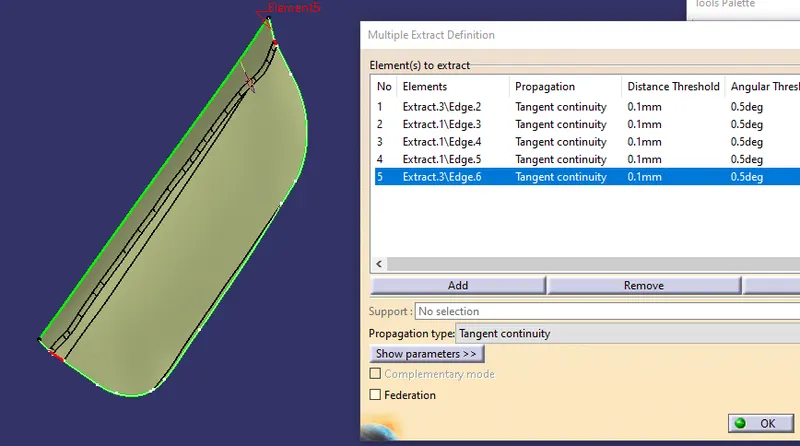
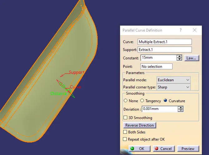
Avoid creating the points near by the locators to avoid the plastic defects.
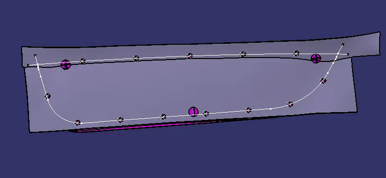
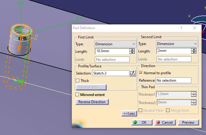
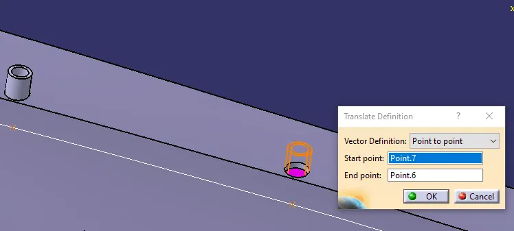
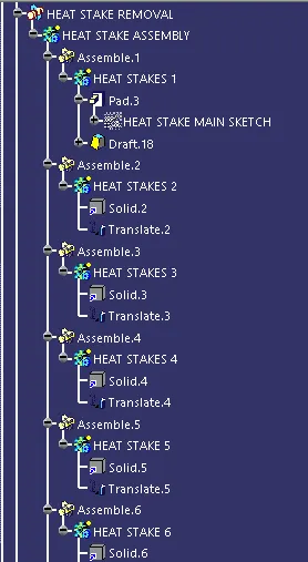
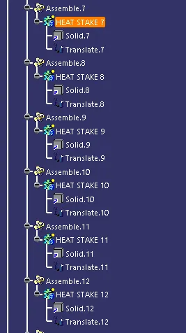
Create the sketch in the reference points for an heat stake , padup the sketch to a solid and translate the created solid to the other poings using point to point feature in translation. Ensure the height of the Heat stake should be lower than than 4 way and 2 way locators, because they assemble first in a locator foolowed by a heat stake.
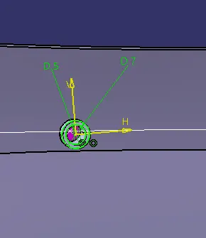
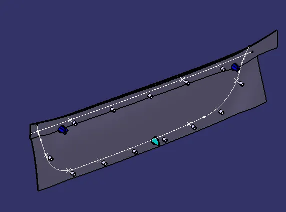
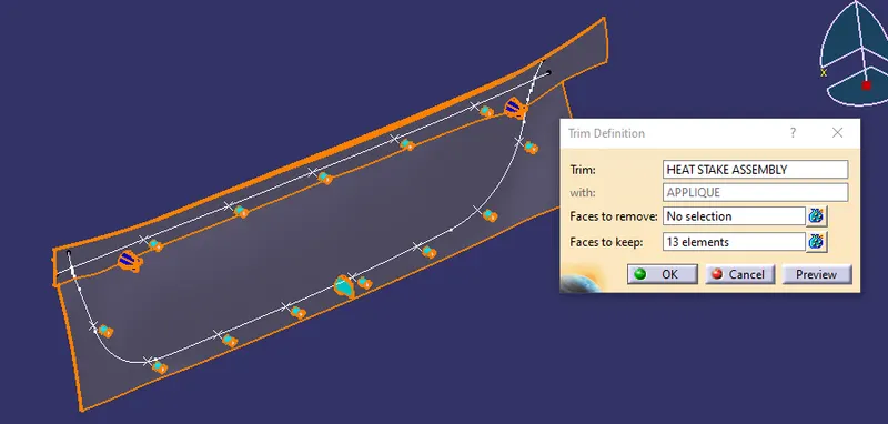
After all the Heat Stake was created untrim the extended parts outside of the class A to a single solid element.
COUNTER PART CLEARENCE
Next create a counter part clearence of 0.1mm for 4 way and 2 way locators and also to the all Heat Stake. The counter part clearence is used to fill the melting plastic in a gap for assemble.
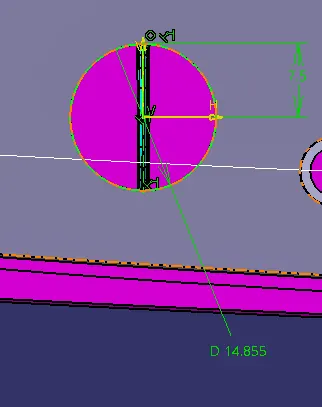
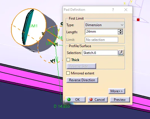
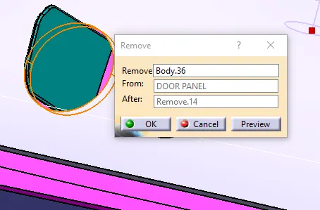
Use same sketch used for 4way locator change the dimension of the circle with 0.1mm clearence. Padup the sketch less than the height of locator to apply the draft and add to main part body by remove coomand.
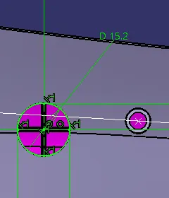
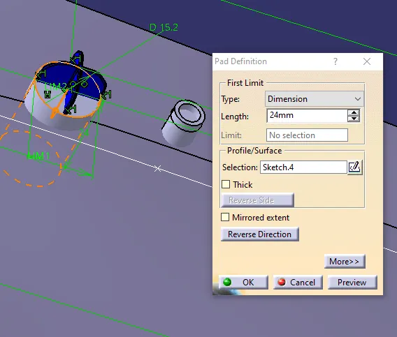
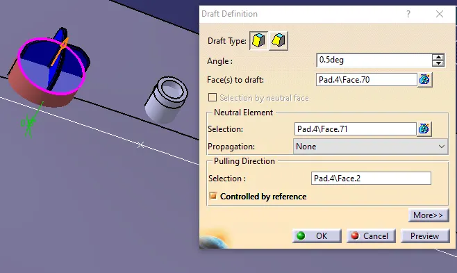
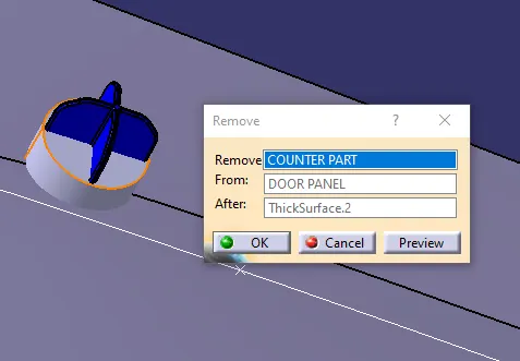
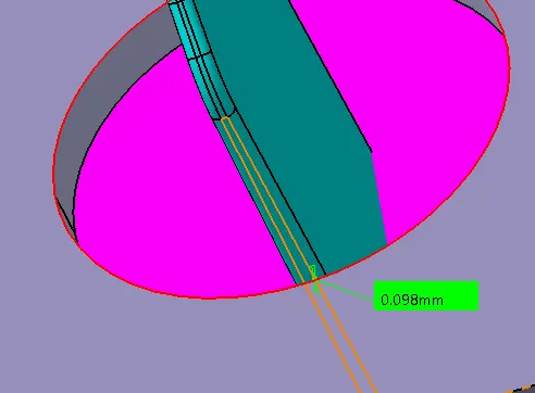
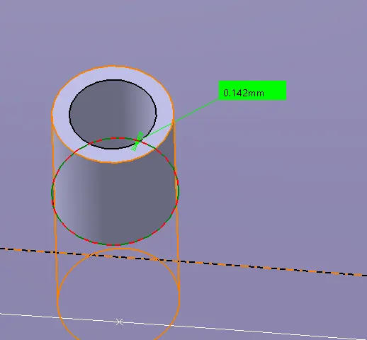
Ensure the clearence value of the locator by measurement.
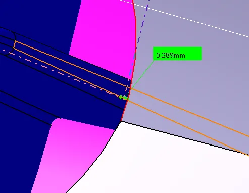
Its showing as 0.289mm clearence due to the extension of hollow surface by draft angle , so we have to adjust the circle dimension according to the draft angle clearence.
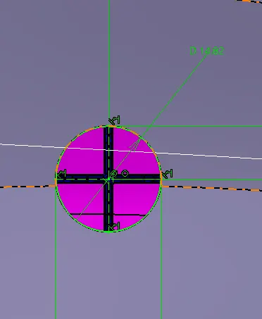
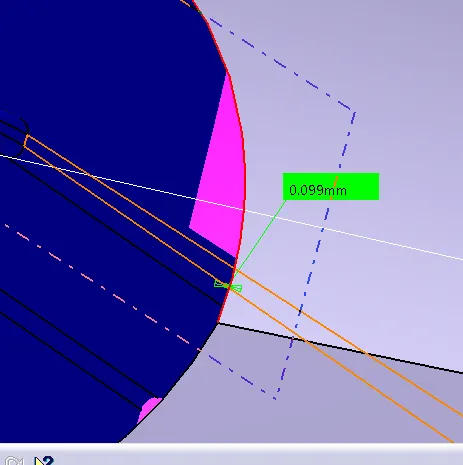
So, with the 14.82mm of dia we are getting 0.1mm clearence for an locator. Translate the remove part to the another 4 way locator by coordinate values.
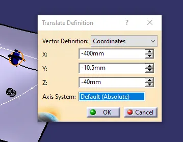
Same as to be done for an 2 way locator too. Copy the same sketch and change the diameter, Padup to some extent both side of the surface and remove them with the door panel body.
HEAT STAKE COUNTERPART CLEARENCE
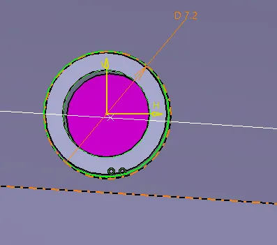
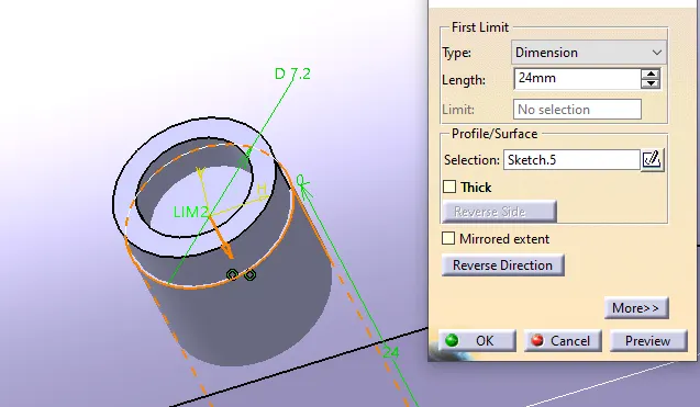
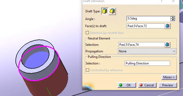
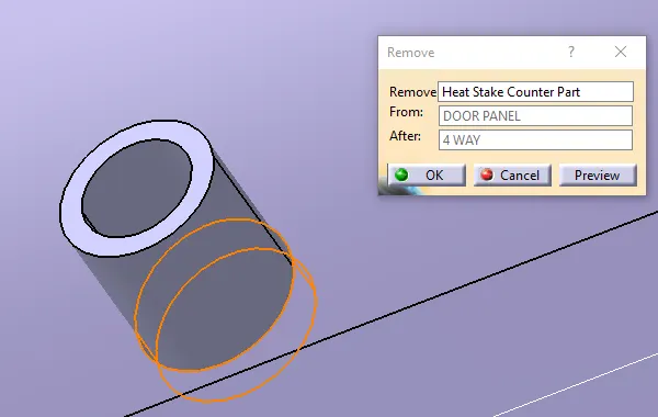
DRAFT ANALYSIS ON PART MODEL
SKETCH SOLVING STATUS
*4 Way Locator
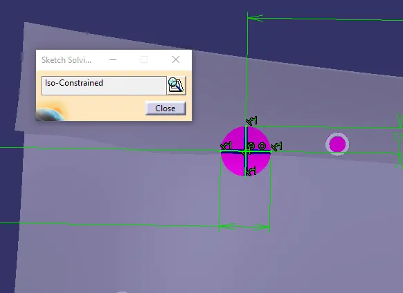
2 Way Locator Sketch
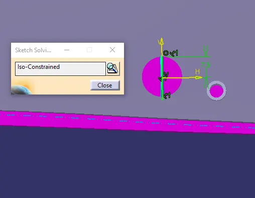
HEAT STAKE SKETCH
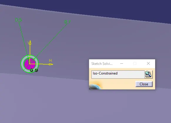
COUNTER PART 4 WAY LOCATOR
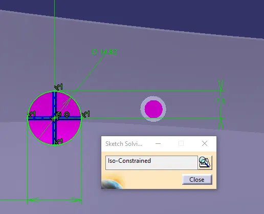
COUNTER PART HEAT STAKE
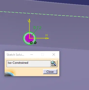
COUNTER PART 2 WAY LOCATOR
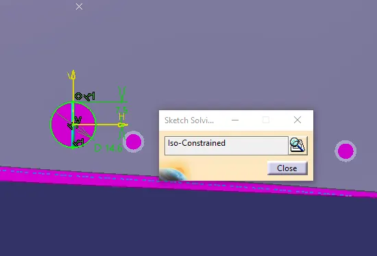
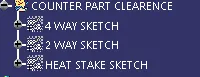
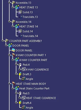
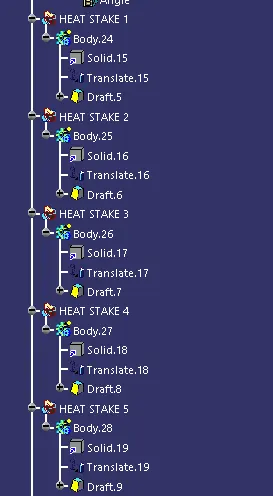
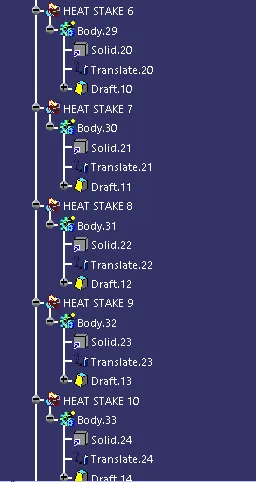
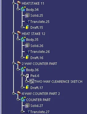
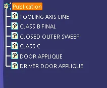
GEOMETRICAL SETS
DIFFERENTIAL VIEWS
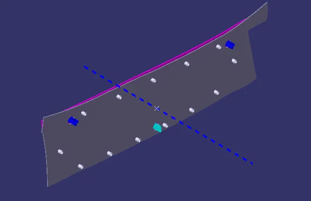
- ISOMETRIC VIEW
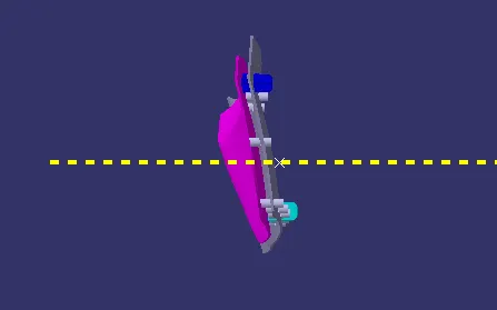
- FRONT VIEW
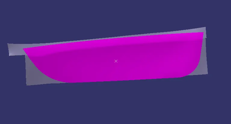
- SIDE VIEW
- TOP VIEW