Roof challenge
ROOF DESIGN
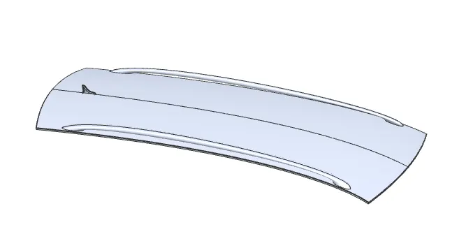
- An automobile roof or car top is the portion of an automobile that sits above the passenger compartment, protecting the vehicle occupants from sun, wind, rain, and other external elements.
- The roof is designed according to the region we need. The materials and design requirements are differ from region to region.
- In India most of the roof are designed with the roof rail system to keep the luggage during the travel.
DESIGN CONSIDERATIONS
- REGION AREA
- MATERIAL SELECTION
- THICKNESS OF ROOF
- HEAT DISTORTION CALCULATION
- SNOW LOAD CONDITION
- HEAD ROOM CLEARENCE
- VISIBILITY CRITERIA
- DEEP DRAWING PROCESS
TYPES OF ROOF USED IN THIS MODEL
- FRONT ROOF
- REAR ROOF
- BOW ROOF-I
- BOW ROOF-II
- BOW ROOF-III
- CENTER ROOF
FRONT ROOF DESIGN
Master section
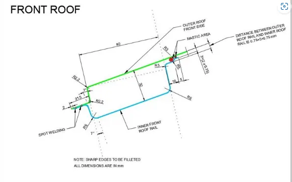
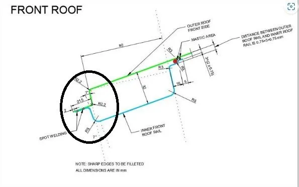
- In the Master section the dimensions which are given as some specific reasons behind it. For example the 7 degree ope angle which given in the styling end point is due to the deep drawing process. In sheet metal the minimum draft angle as to be 7 degree. Same as 21.5mm distnace dimension is for the assemble of windshield. The fillet radius should be 3mm+thickness of the part(0.75mm).
- The distance 80mm of the inner panel is to maintain the head room clearence of the driver, the minimum 80mm is needed to have proper structure of the roof. So that it matches every dimensions clear. It may vary depends on the driver seating area.
- The inner panel distance of 32mm is kept for the Visibility section for the driver. Those values are given by the project management team.
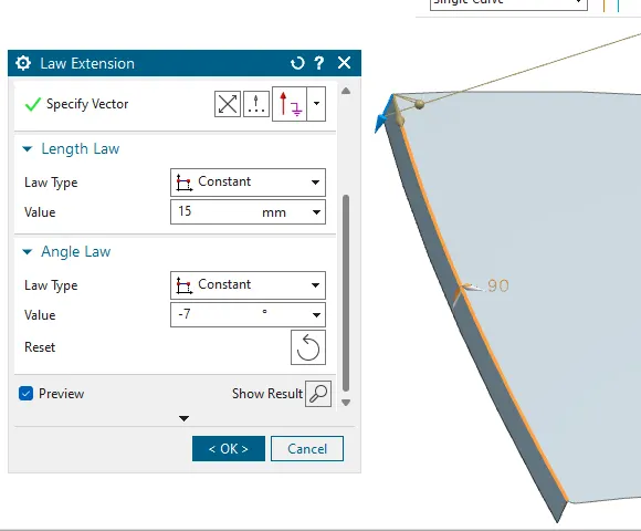
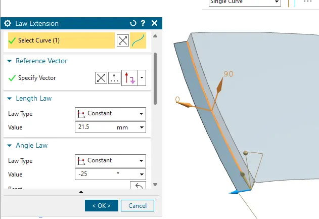
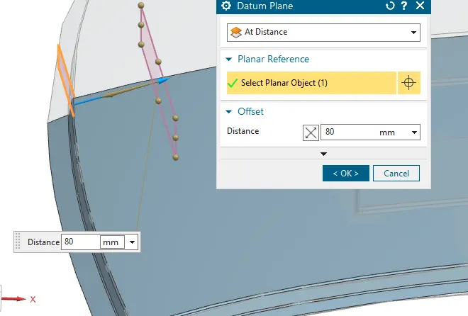
- The distance 80mm for the front roof is trimmed by the datum plane through the inersection curve.
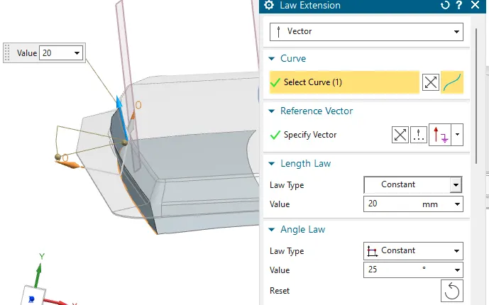
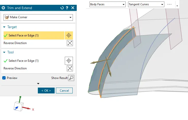
- The surface is offset as per the dimension given in the master section of 6.5 & 4.5mm respectively length of 10mm and 5mm. It can be joined by the studio surface with linear relation zero degree.
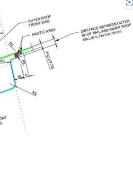
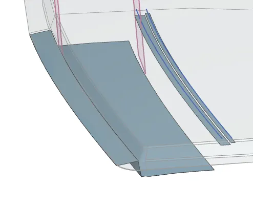
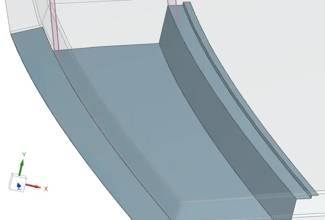
- The face blend and edge blend is applied according to the master section.
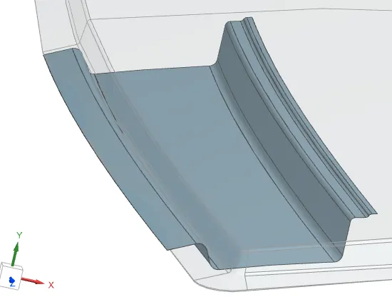
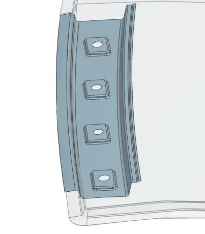
- To increase the strength of the component, we had added the emboses to the roof.
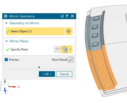
MIRROR GEOMENTRY
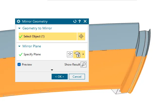
Mirror the created surface to the other side using the the mirror geomentry feature with refrence as a datum coordinate system plane.
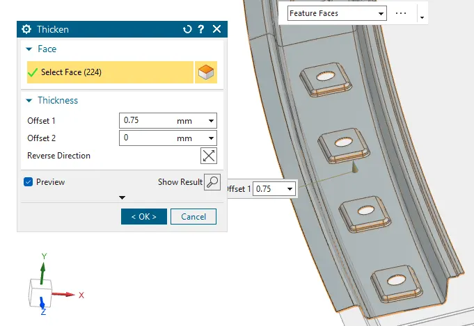
THICKNESS
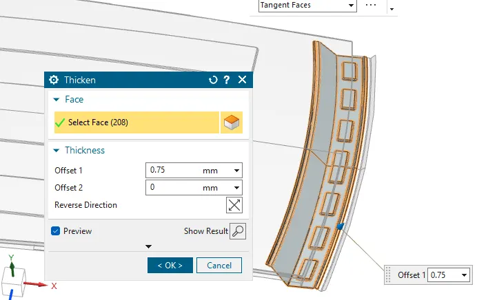
- The thickness is given as the final operation to the roof. The standard thickness used in the OEM'S is 0.75mm.
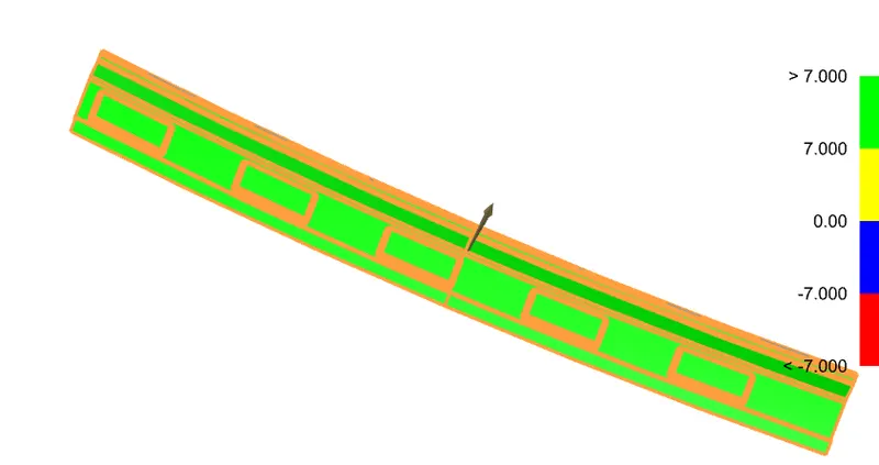
DRAFT ANALAYSIS
SECTION VIEW
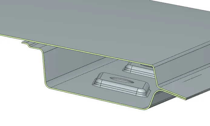
REAR ROOF DESIGN
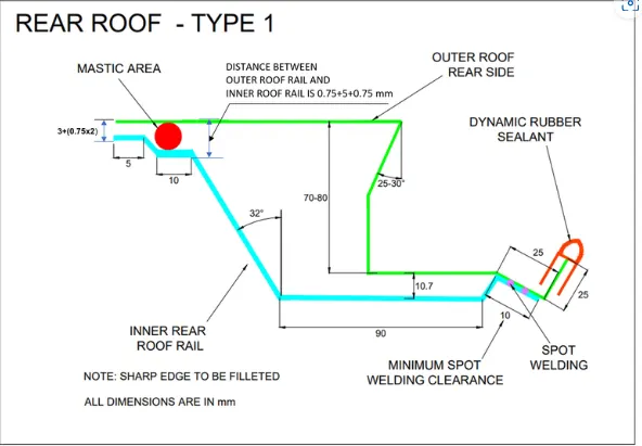
Master Section of Rear Roof
DIMENSION EXPLANATION
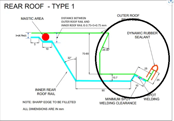
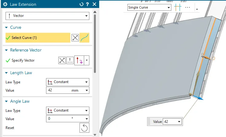
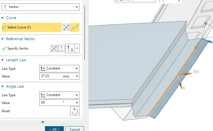
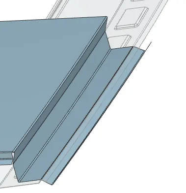
- The angle of 25 to 30 degree is to take the material inwards of the roof rail for the back door assemble.
- The offset distance of 70-80 is same as for Head Room clearance and Visibility. And also the Back door assemble is done here with the Hinge reinforcement, movealble of back door motion.
Outer Panel Area
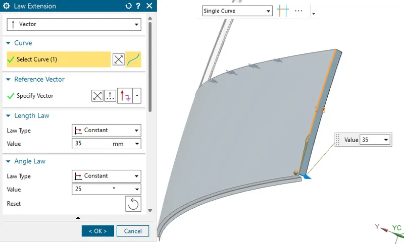
INNER PANEL AREA
Rear Roof with Full Blend
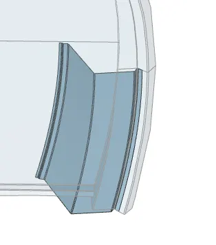
MIRROR GEOMENTRY
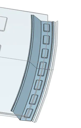
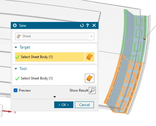
SEW THE COMPONENT
THICKENESS
SECTION-VIEW
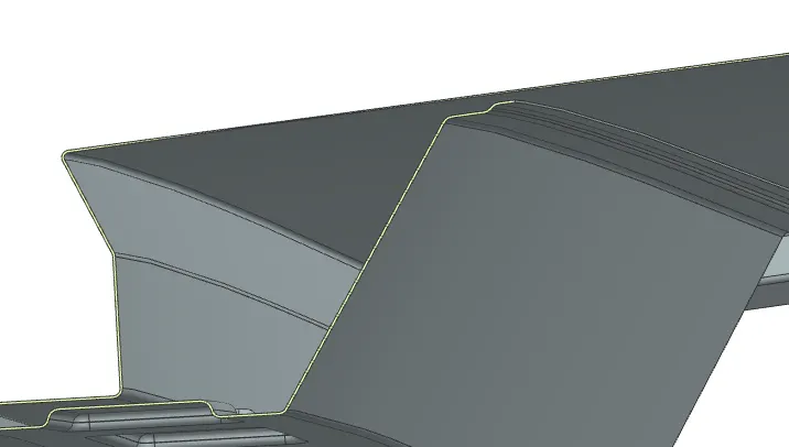
DRAFT ANALYSIS

BOW ROOF MODELS
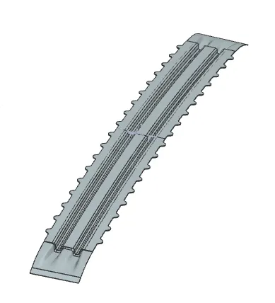
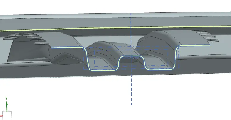
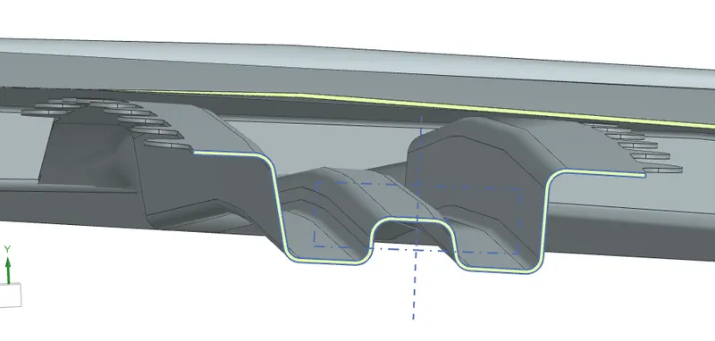
The major reason to have a bow roof is to give strength to the outer roof which have flater surface. In order to tilt the surface we are adding the bow roof to the outer roof rail.
BOW ROOF-I
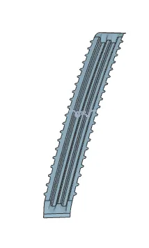
The Design of Bow roof is to add strength to the outer roof rail so that roof wont crush as much as easy. The position of the bow roof is determined by the reference position of the front roof.
MASTER SECTION
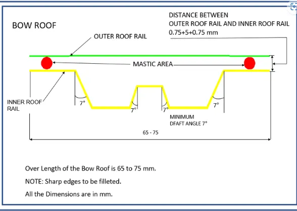
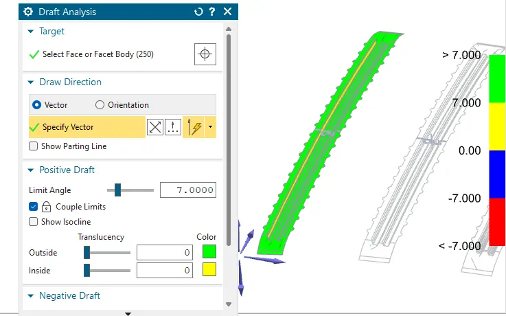
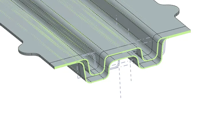
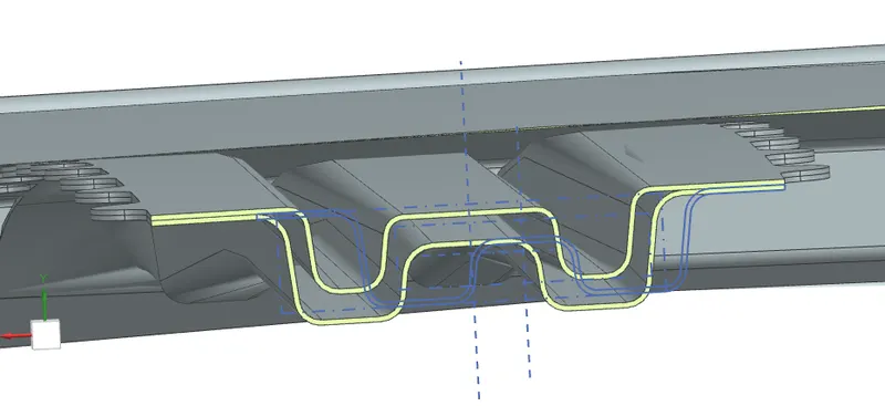
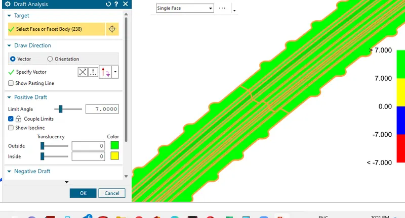
- The length of the roof is to 65-75mm with the minimum draft angle of 7 degree.
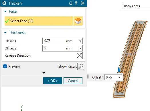
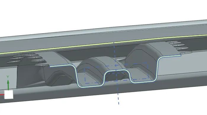
- The distance between the outer roof and bow roof is 6.5 mm, so that thickness of each roof 0.75mm*2 = 1.5mm. So the gap which we have after the thickned part is 5mm which is enough to have mastic between them. Minimum distance to have mastic is 5mm.
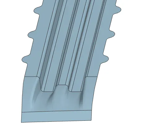
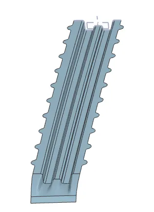
DRAFT ANALYSIS
SECTION-VIEW
CENTER ROOF WITH REINFORCEMENT ROOF
MASTER SECTION
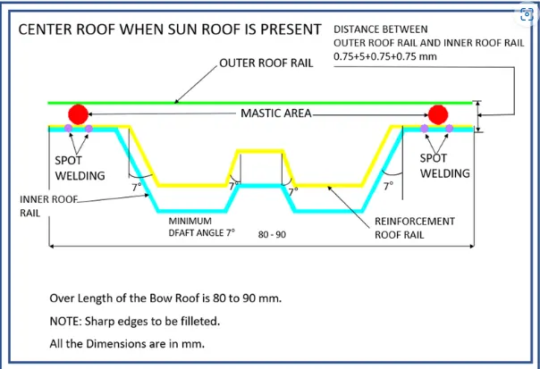
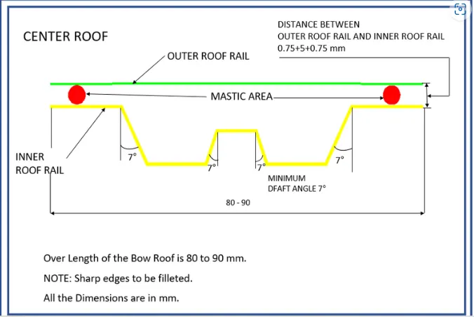
- Center Roof design is designed with sunroof and without sunroof. Without Sunroof there is no need of reinforcement roof to be added.
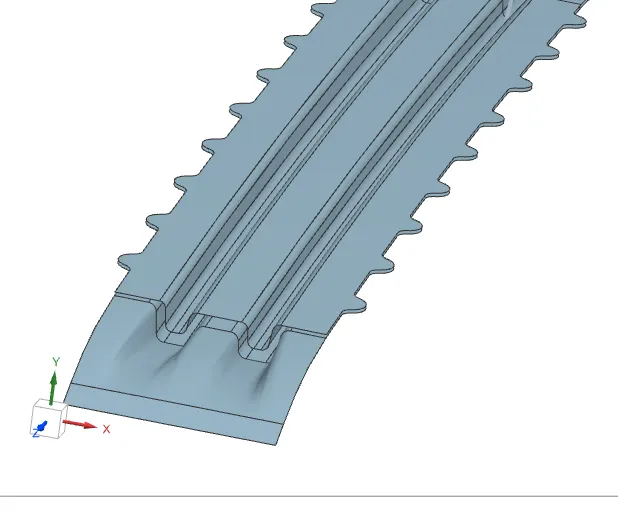
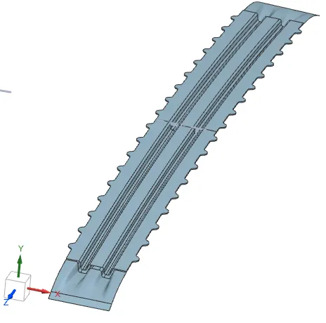
- With Sunroof the reinforcement roof is added to give strength to the outer roof. It can improve the center area strength.
CENTER ROOF WITHOUT REINFORCEMENT ROOF CENTER ROOF WITH REINFORCEMENT ROOF
THICKENED PART
SECTION VIEW
DRAFT ANALYSIS

SECTION-VIEW
DESIGN OF BOW ROOF-II
DRAFT ANALYSIS
SECTION VIEW
DESIGN OF BOW ROOF-III
DRAFT ANALYSIS
SECTION VIEW
MATERIAL SELECTION FOR ROOF MODEL
- GALVALUME STEEL(SP121BQ)
Made with the traditional hot-dipping process, Galvalume is a suitable match for applications that demand high corrosion resistance and heat reflectivity. They can use it across applications like construction, appliances, agricultural equipment, and several non-exposed automotive components.
- STRUCTURAL STEEL(SP231-440PQ
Automotive structural steel is used to provide greater strength to vehicle components. High strength of steel can be achieved by mixing alloy materials and cooling at low temperature. Additionally, automotive structural steel has excellent cold forming ability.
- GALVANNEALED STEEL(SP783AJQ)
Galvannealed (or galvanneal) Steel is a carbon steel sheet coated with zinc on both sides by the continuous hot-dip process. Immediately as the strip exits the coating bath, the molten zinc coating is subjected to an in-line heat treatment that converts the entire coating to a zinc-iron alloy.
JOINING PROCESS
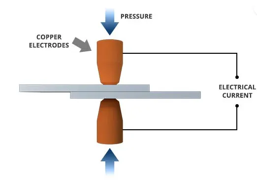
The roof assembly and joining process can be done by two process,
- SPOT WELD
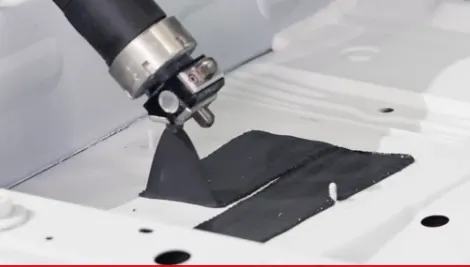
- MASTIC SEALENT
JUSTIFICATION OF ROOF POSITION & CURVATURE STUDY
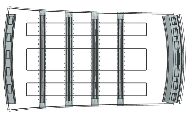
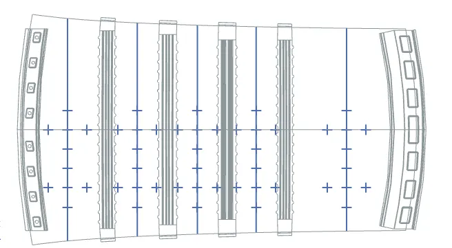
The Curvature study is to justify the bow roof placement position before submitting to the simulation team. The bow roof position is depend upon the curvature of the outer roof rail.
The curvature Study is classified into two types
- Heat distortion calculation
- Snow Load condition
HEAT DISTORTION CALCULATION
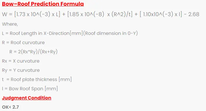

Hence, the calculations are done the condition value for all the scenarios is look's good which as placed <2.7. So, the bow roof positions which has placed had been ok.
SNOW LOAD CALCULATION
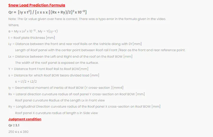
SECTION MODULUS & INERTIA
BOW ROOF-I
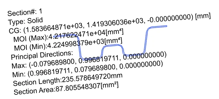
BOW ROOF-II
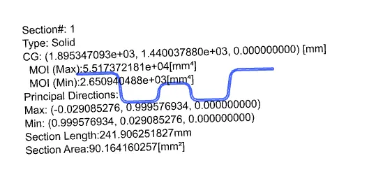
CENTER ROOF
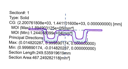
BOW ROOF-III
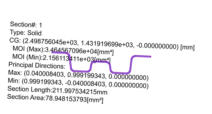

The Snow load calculation for the all the stages looks good, So the bow roof are placed at right place & condition. The Snow load condition is to test the strength of the outer roof rail. The Snow load is comes to play in a snow fall areas as European & U.S.A. countries. The bow roof has to sustain the load of the snow fall.
If the snow load condition fails, we can add an embosses to the outer roof rail to improve the roof strength.
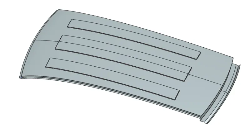
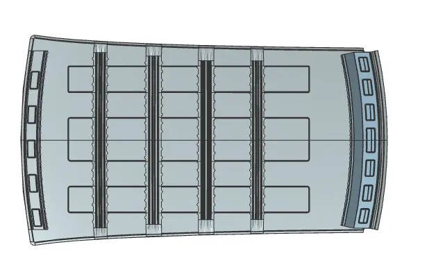
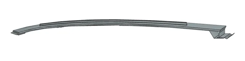
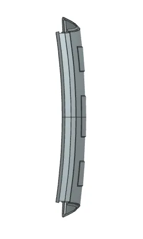
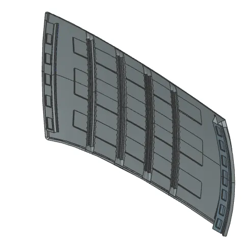
DIFFERENTIAL VIEWS OF ROOF DESIGN
CONCLUSION
Hence, the Roof model has been designed with the standard dimension with curvature study and joining process.