Creating Different Connectors in Hypermesh
OBJECTIVE:
To create connector and attach the various parts of the given model
1. Right_Rail_2 & Front_truss_1:- Seam-Quad(angled+capped+L)
2. Left_Rail_2 & Front_truss_1:- Quad elements
3. Front_truss_2, Front_truss_1 & Right_Rail_1:- Spot weld with 3 Layers and 5 mm Diameter
4. Front_truss_2, Front_truss_1 & Left_Rail_1:- Hexa (Adhesive)
5. Rear_truss_2 & Right_Rail_2:- Bolt Connector
6. Rear_truss_2 & Left_Rail_2:- Bolt Connector
7. Right_Rail_1 & Right_Rail_2:- Spot-weld with Rigid Elements
8. Left_Rail_1 & Left_Rail_2:- Spot-weld with Spring Elements
9. Rest all the component left Join them with suitable connectors
THEORY: Connectors
The Connectors module in hyperworks contains several connector-specific panels that can be used to create and manage connectors.
Connectors may be 1-D, 2-D, 3-D elements that connects two or more components.
PROCEDURE:
1. Import the model in hyperworks in Radioss user profile.
2. Since the model already has mid surfaces proceed to automeshing by given element size as 5 with mixed type. Also tweek the mesh for a better mesh flow.
3. to apply different connectors, every connector was seperately added to the respective components.
[Note: Property and material of the connectors and the assembly are not created.]
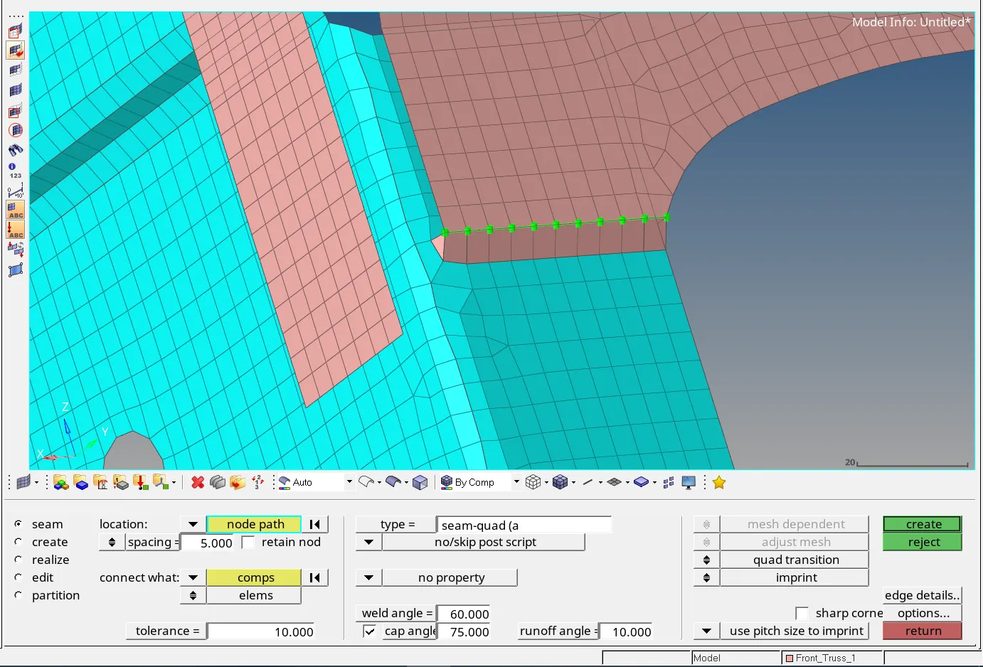
[1] Right_Rail_2 & Front_truss_1:- Seam-Quad(angled+capped+L)
Seam-Quad(angled+capped+L) also called Volvo Seam quad connector is created by:
1D > Connectors > Seam
Type: Seam-quad(angled capped L)
Location: Nodelist > By path > select the nodes on the edge where the connector is to be created. > Select components
Spacing: 5 (as element size taken was 5mm)
Tolerance: 10
Weld angle:
Cap angle:
run off angle:
The connector so created is shown in the image below.
[2] Left_Rail_2 & Front_truss_1:- Quad elements
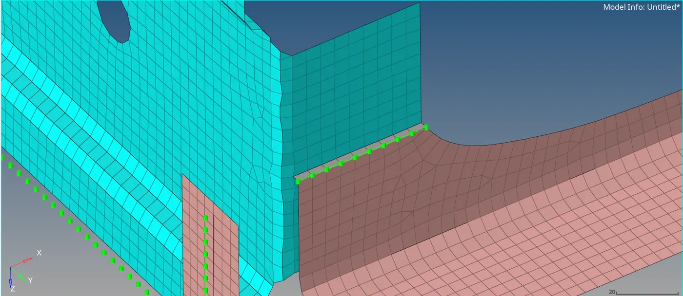
To create quad elements perform the following steps
1D > Connectors > Seam
Type: Quads
Location: Nodelist > By path > select the nodes on the edge where the connector is to be created. > Select components
Spacing: 5 (as element size taken was 5mm)
Tolerance: 10
The connector so created is shown in the image below.
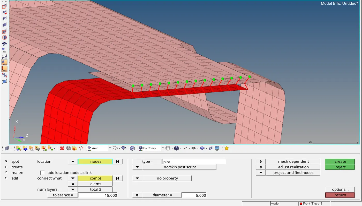
[3] Front_truss_2, Front_truss_1 & Right_Rail_1:- Spot weld with 3 Layers and 5 mm Diameter
To create the spot weld with above perimeters following steps were taken
1D > Connectors > Spot
Type: Plot
Location: Nodelist > By path > select the nodes on the edge where the connector is to be created. > Select components
Spacing: 5 (as element size taken was 5mm)
Tolerance: 10
Num layers: total 3
Diameter: 5
The connector so created is shown in the image below.
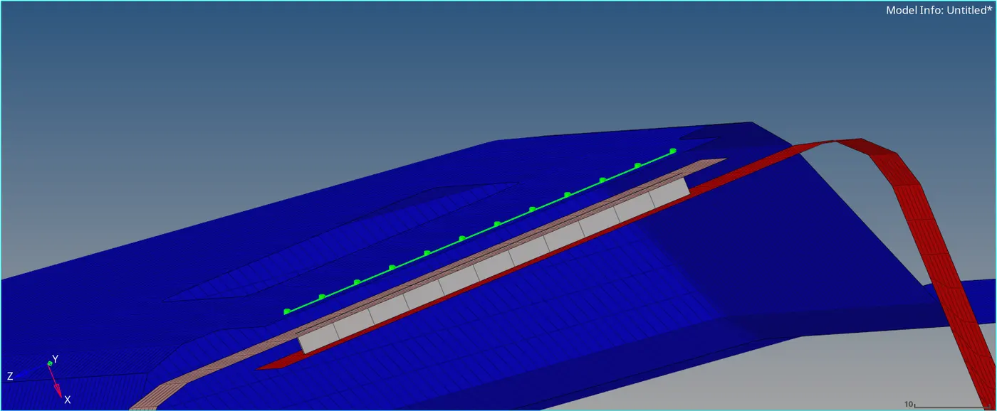
[4] Front_truss_2, Front_truss_1 & Left_Rail_1:- Hexa (Adhesive)
To apply Hexa(adhesive) to the given components following steps were taken.
1D > Connectors > Seam
Type: Hexa (adhesive)
Location: Nodelist > By path > select the nodes on the edge where the connector is to be created. > Select components
Spacing: 5 (as element size taken was 5mm)
Tolerance: 10
Strips = 1, Coates = 1, Width = 1
The connector so created is shown in the image below.
[5] Rear_truss_2 & Right_Rail_2:- Bolt Connector
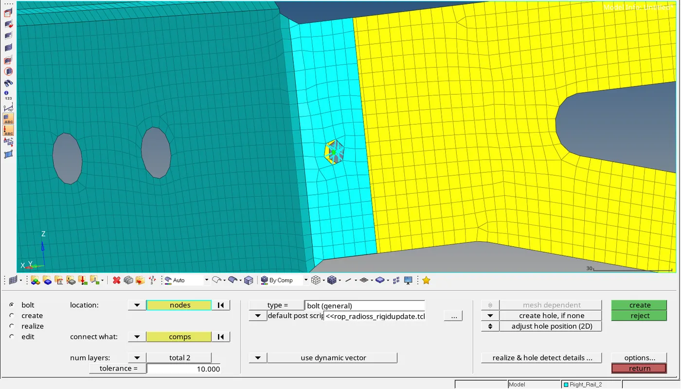
To create a bolt connector following steps were taken.
1D > Connectors > Bolt
Type: Bolt (general)
Change consider existing hole to create hole, if none
Location: Nodelist > select the node where bolt has to be created.
Connect what: Comp > select the components along which the bolt has to be created.
Num Layer: total 2
Tolerance: 10
The connector so created is shown in the image below.
[6] Rear_truss_2 & Left_Rail_2:- Bolt Connector
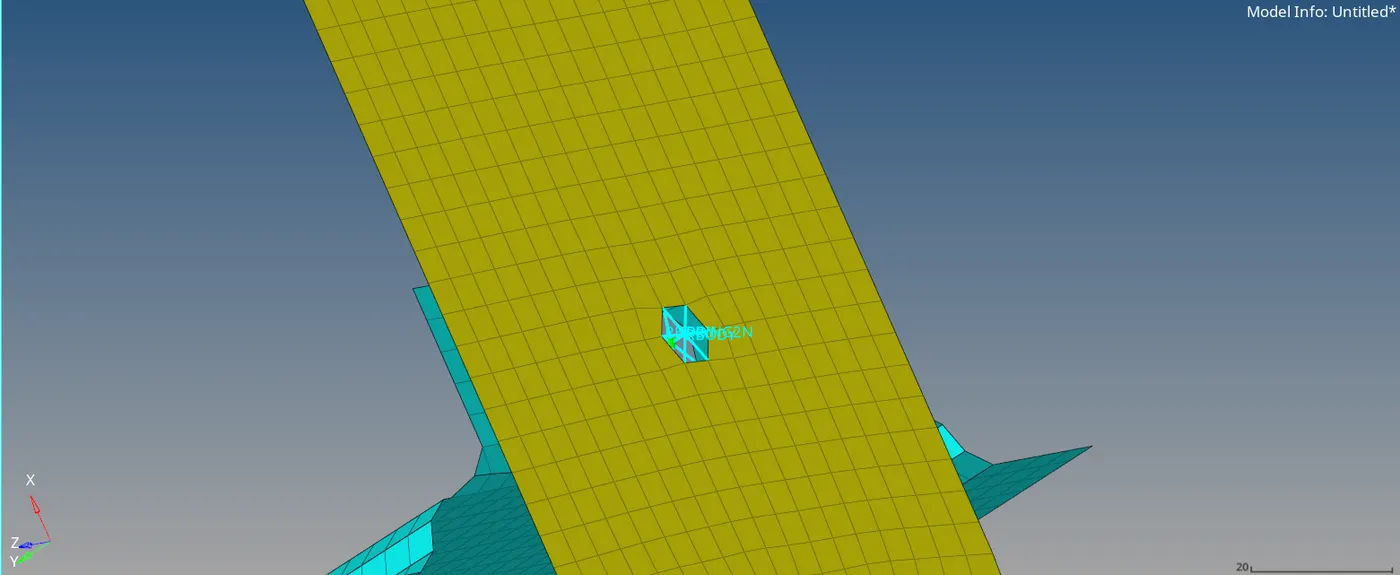
To create the bolt connector similar steps were taken as in part 5.
The connector so created is shown in the image below.
[7] Right_Rail_1 & Right_Rail_2:- Spot-weld with Rigid Elements
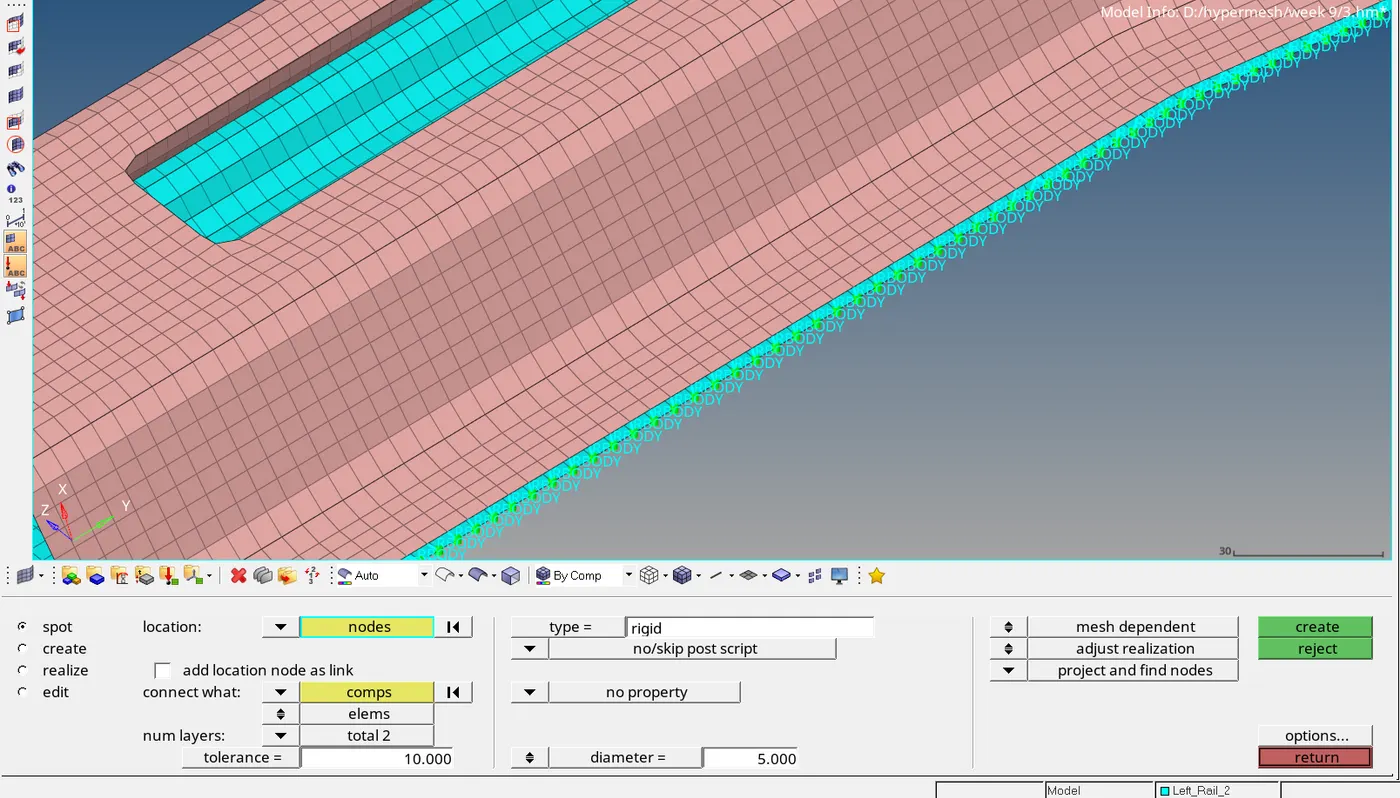
Spot weld with rigid elements creates RBE2 elements to connect the components.
Spot Weld with rigid elements can be created by the following steps.
1D > Connectors > Spot
Type : Rigid elements
Location: Nodelist > By path > select the nodes on the edge where the connector is to be created. > Select components
Spacing: 5
Tolerance : 10
Diameter : 5
Num Layers: Total 2
The connector so created is shown in the image below.
[8] Left_Rail_1 & Left_Rail_2:- Spot-weld with Spring Elements
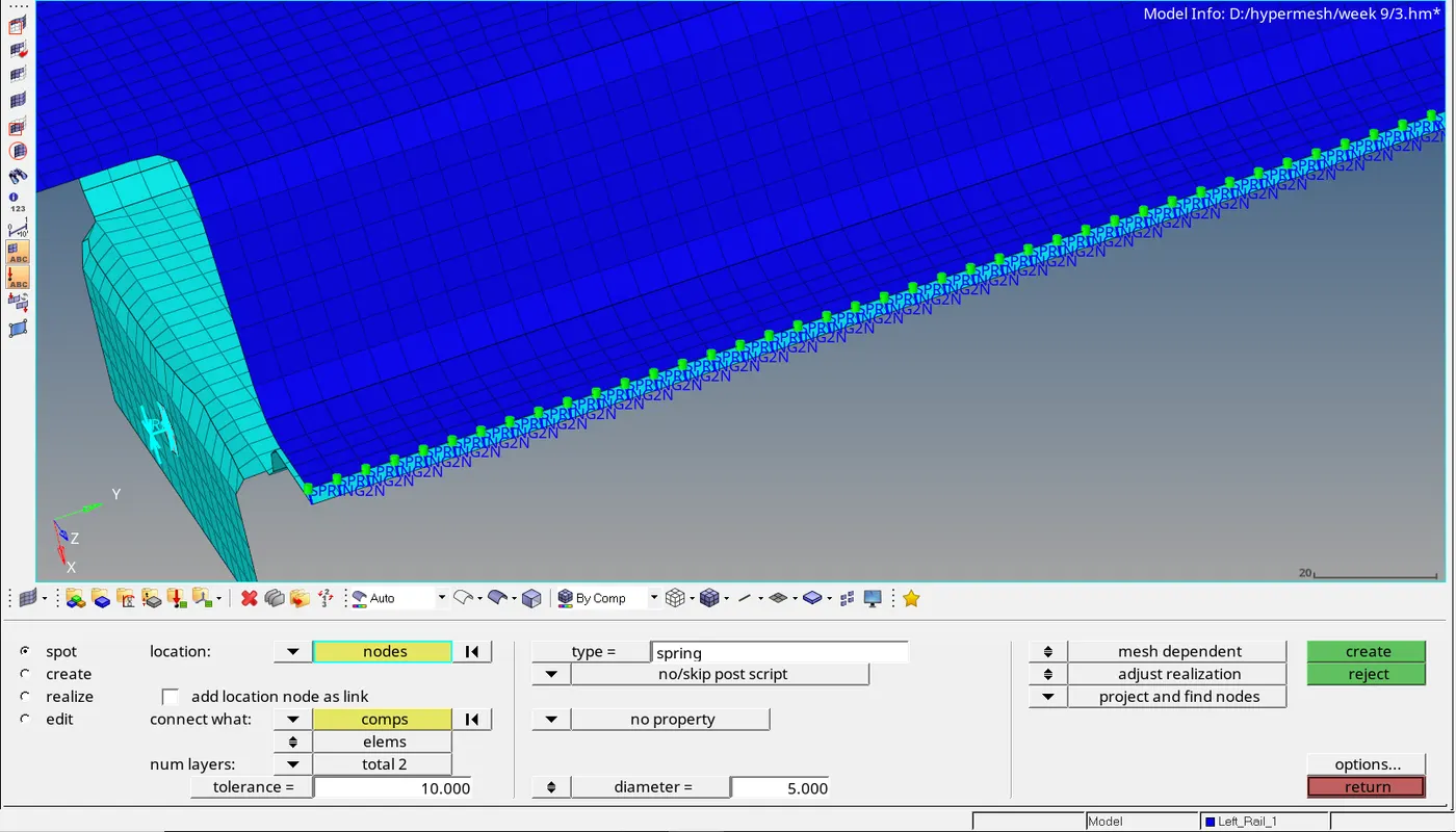
Spot weld with spring elements can be created with similar process.
Spot Weld with spring elements can be created by the following steps.
1D > Connectors > Spot
Type : Spring
Location: Nodelist > By path > select the nodes on the edge where the connector is to be created. > Select components
Spacing: 5
Tolerance : 10
Diameter : 5
Num Layers: Total 2
The connector so created is shown in the image below.
[9] Rest all the component left Join them with suitable connectors
steps followed by the below connectors are similar to the above parts.
a) Left_Rail_1 & Rear_Truss_2:- Bolt Connector
b) Rear_Truss_1 & Rear_Truss_2:- Spot Weld- rigid elements
c) Reinf_Plate & Front_Truss, Reimf_Plate & Front_Truss_2:- Seam-Quad element
d) Right_Rail_1 & Rear_Truss_2:- Bolt Connector
e) Front_Truss_2 & Right Rail 2:- Quad element