Week 9 Challenge
Aim: To create an energy management strategy model with battery, UC and fuel cell for the positive power.
Process:
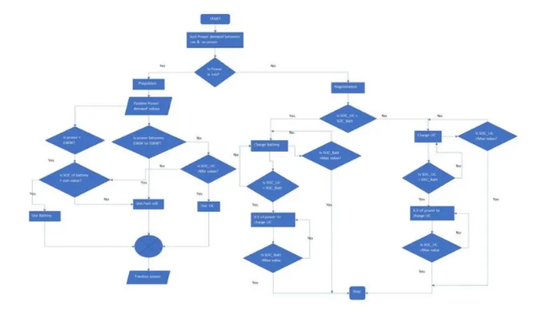
The below flowchart would describe the energy management strategy for an electrical vehicle with battery, UC and fuel cell as energy sources.
Assumptions:
Here let us consider the corresponding power demand and the conditions for energy sources to provide energy.
| positive power demand | conditions | energy source |
| 0-9999 |
|
|
| 10000-22999 |
|
|
| 23000-54999 | No condition | Fuel cell |
| 55000 and above |
|
|
Simulation model:
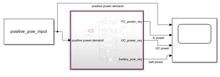
In the model the input positive power demand is taken from the workspace. The subsystem contains the energy management of the energy sources according to the power demands and their corresonding responses are observed.
Steps:
The following figure shows the subsystem that is present in the current model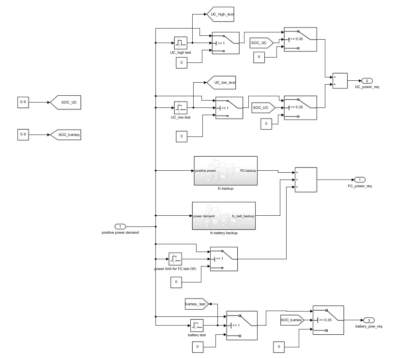 :
:
Steps:
1) Ultracapacitor:
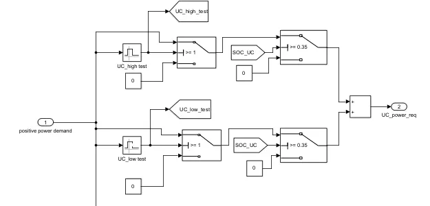
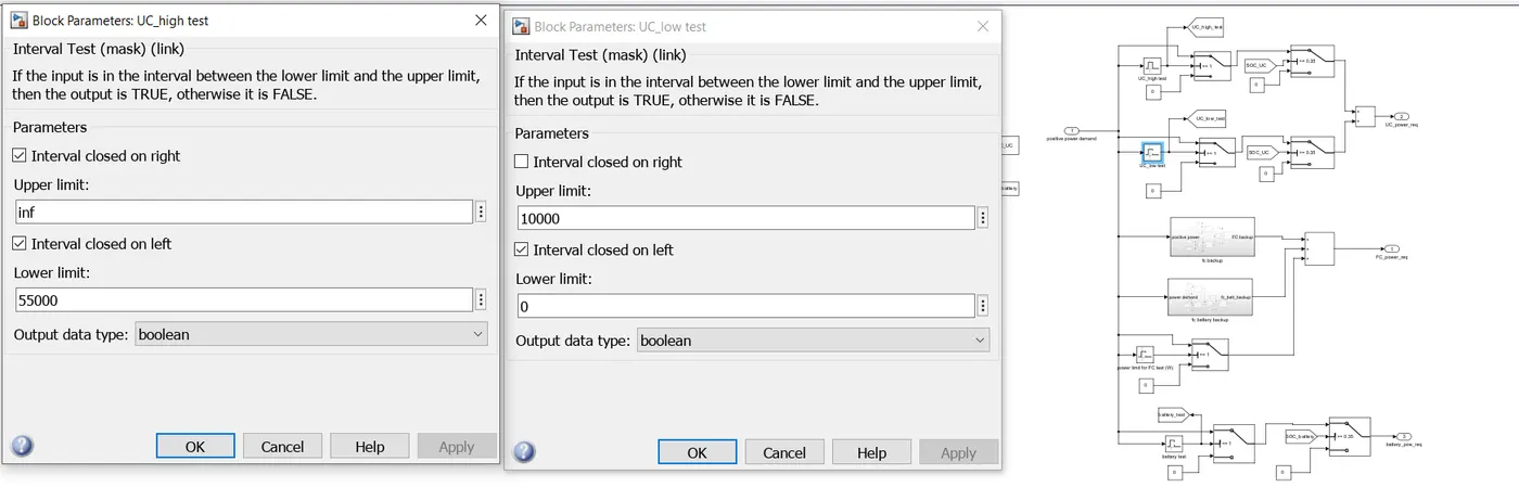
- The ultracapacitor would work in the either for high power demand or for low power demand.
- The ultracapacitor provides good performance for instantaneous power.
- In the above it is divided for the high and low power test.
As in the above figure,
- For the high power demand which is greater than 55000W and aove the UC_high_test is considered. If the power is high and the SOC of UC>0.35 then the UC would act as the power providing source.
- For the low power demand which in between 0W and 10000W the UC_low_test is considered. If the power is in between the range and the SOC of UC>0.35 then the UC would act as the power providing source.
2) Battery:
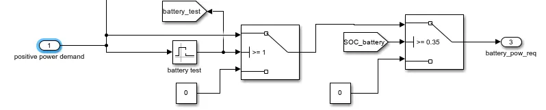
- For the low power demand the battery would be suitable.
- According to the capacity of the battery the power is given to the battery.
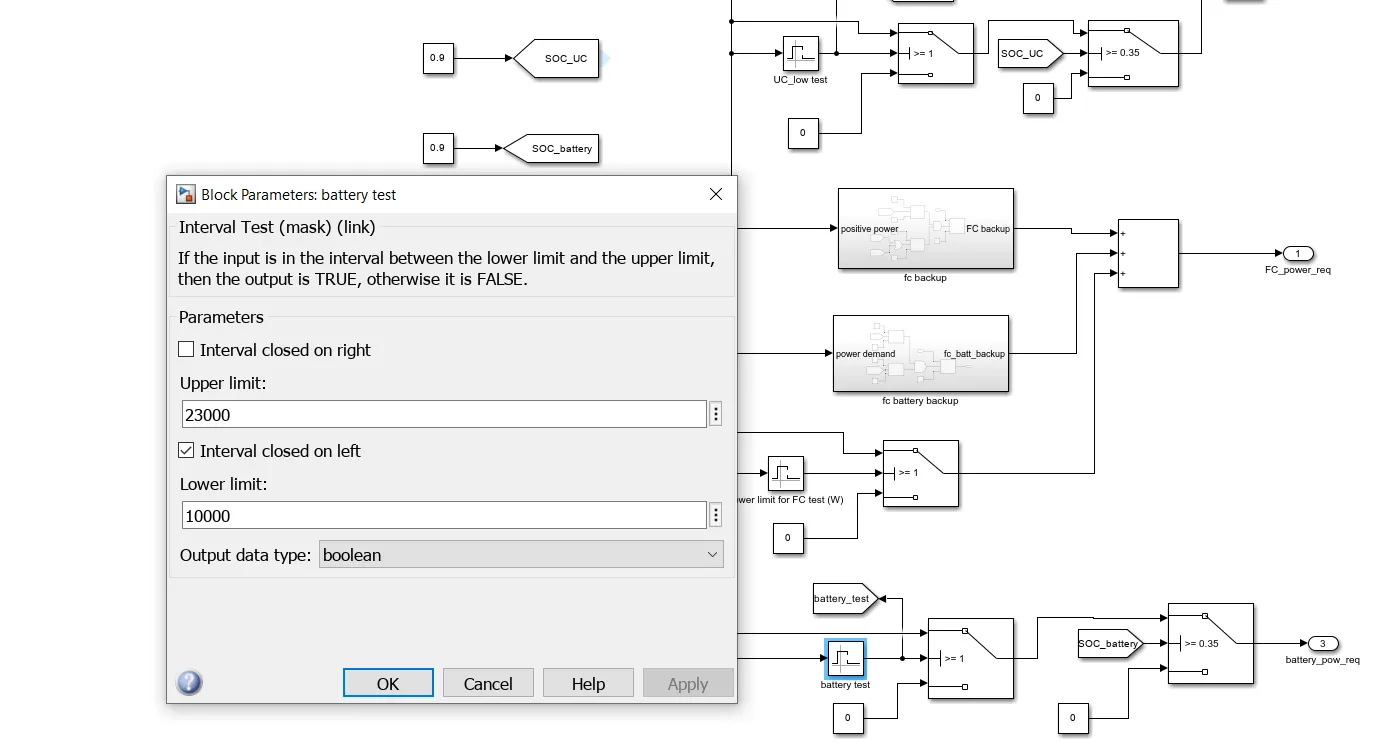
- Here the battery test is considered for the power demand in between 10000W to 23000W.In this battery range the battery would provide the energy if the SOC_battery>0.35.
3) Fuel cell:
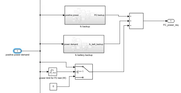
- The fuel cell would provide energy for medium range power demand.
- The fuel cell would cover up the power demand if the ultracapacitor or the battery are unabl to provide the energy due to their low state of charge.
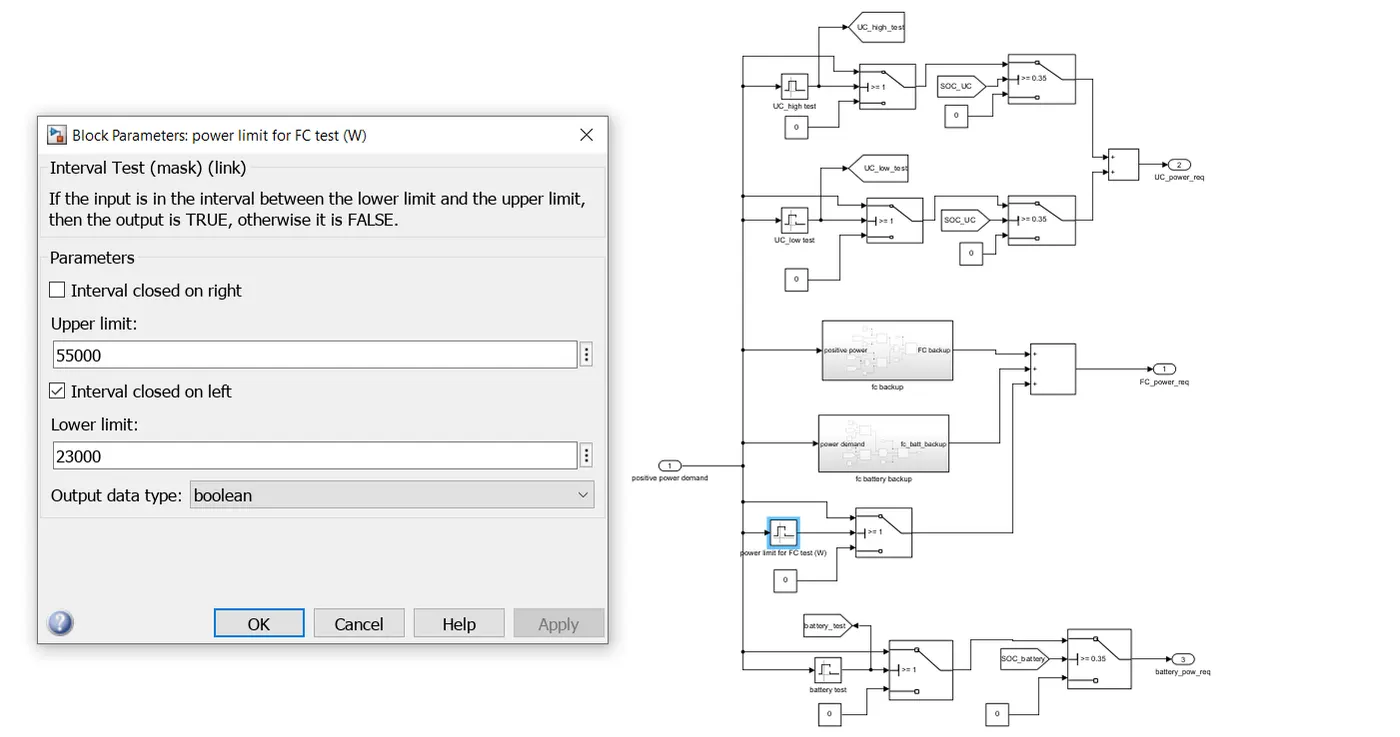
- The fuel cell would work in the power range from 23000W to 55000W.
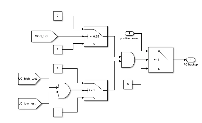
- The Fuel cell would act as the backup source for the ultracapacitor when the SOC_UC<0>
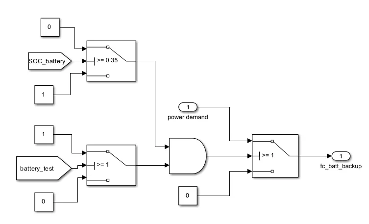
- The Fuel cell would act as the backup source for the battery too when the SOC_battery<0>
Output:
1) Let us consider the SOC_UC=SOC_battery=0.9, the output is as follows:
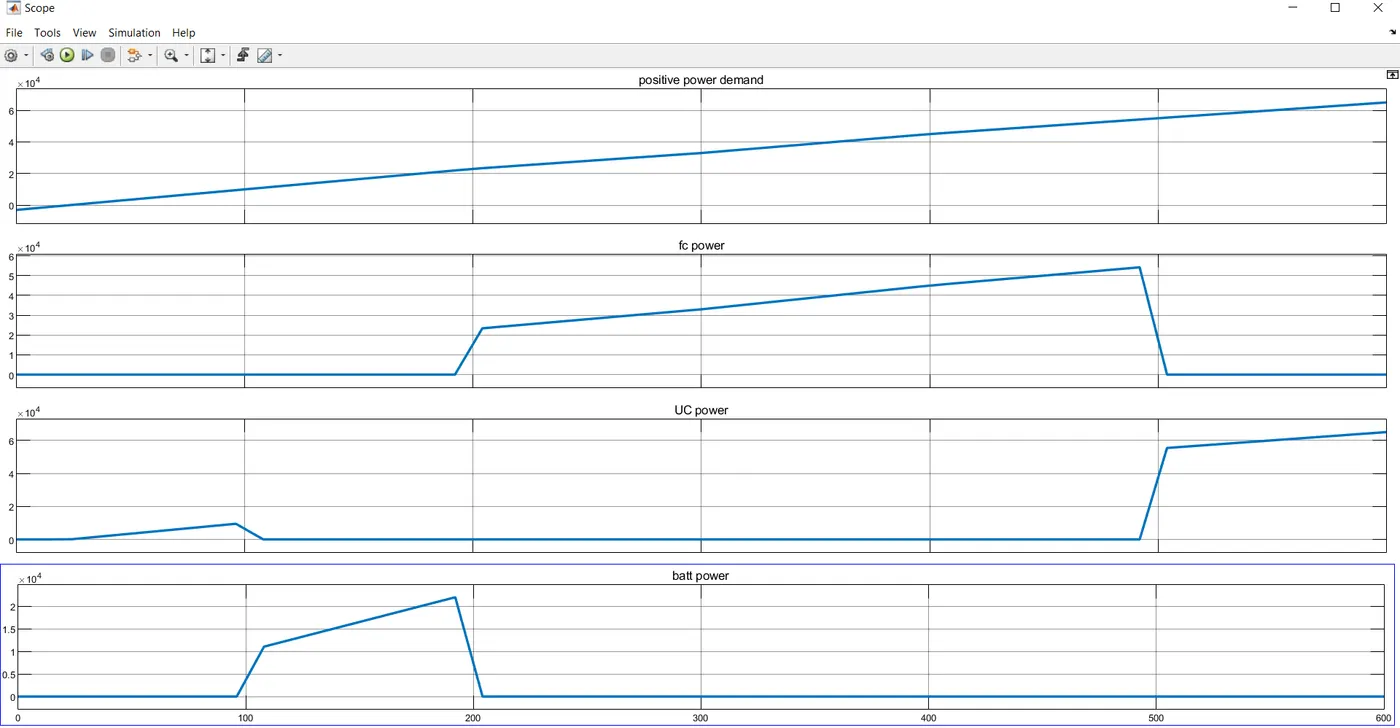
In the above figure it is observed that the fc provided power from 23KW to 55KW, battery provided the power from 10KW to 23KW and the UC provided the power from 0 to 10KW also for 55KW to above.
2) Let us consider the SOC_UC=SOC_battery=0.3, the output is as follows:
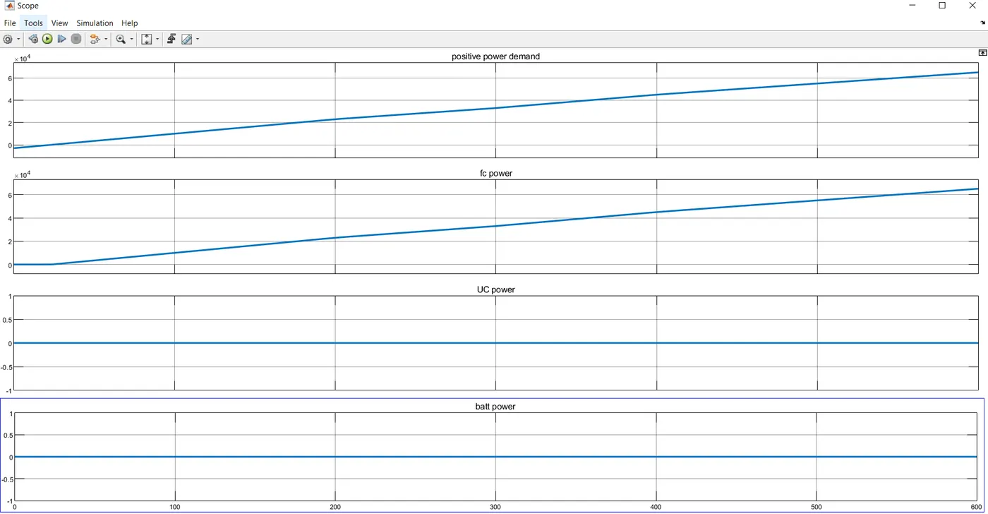
Here as the SOC_UC and SOC_battery are less than 0.35 the fuel cell has powered the vehicle.
3) If SOC_UC=0.3 and SOC_battery=0.6, the output is as follows:
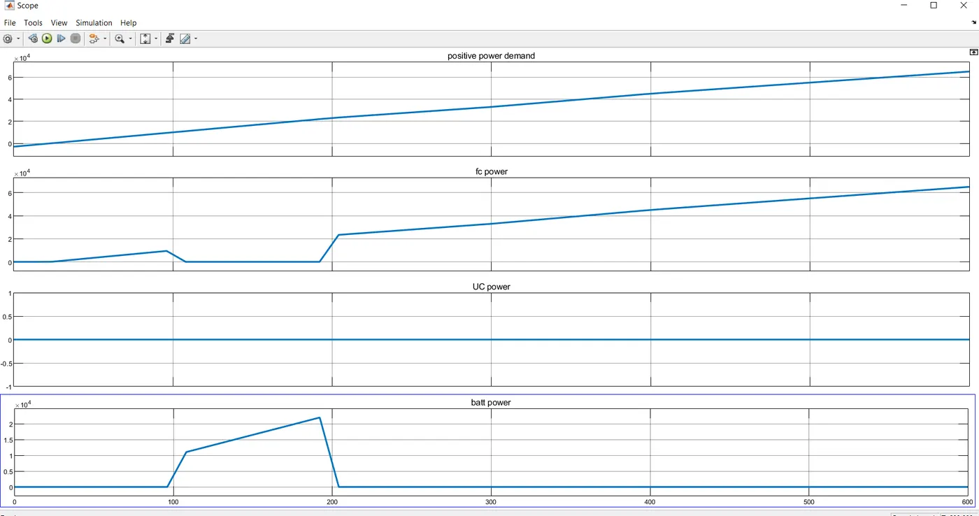
Here it is observed that as the SOC_UC=0.3 the fuel cell has covered up its energy for vehicle and the battery is able to provide the energy for its demand.
4) If SOC_UC=0.6 and SOC_battery=0.3, the output is as follows:
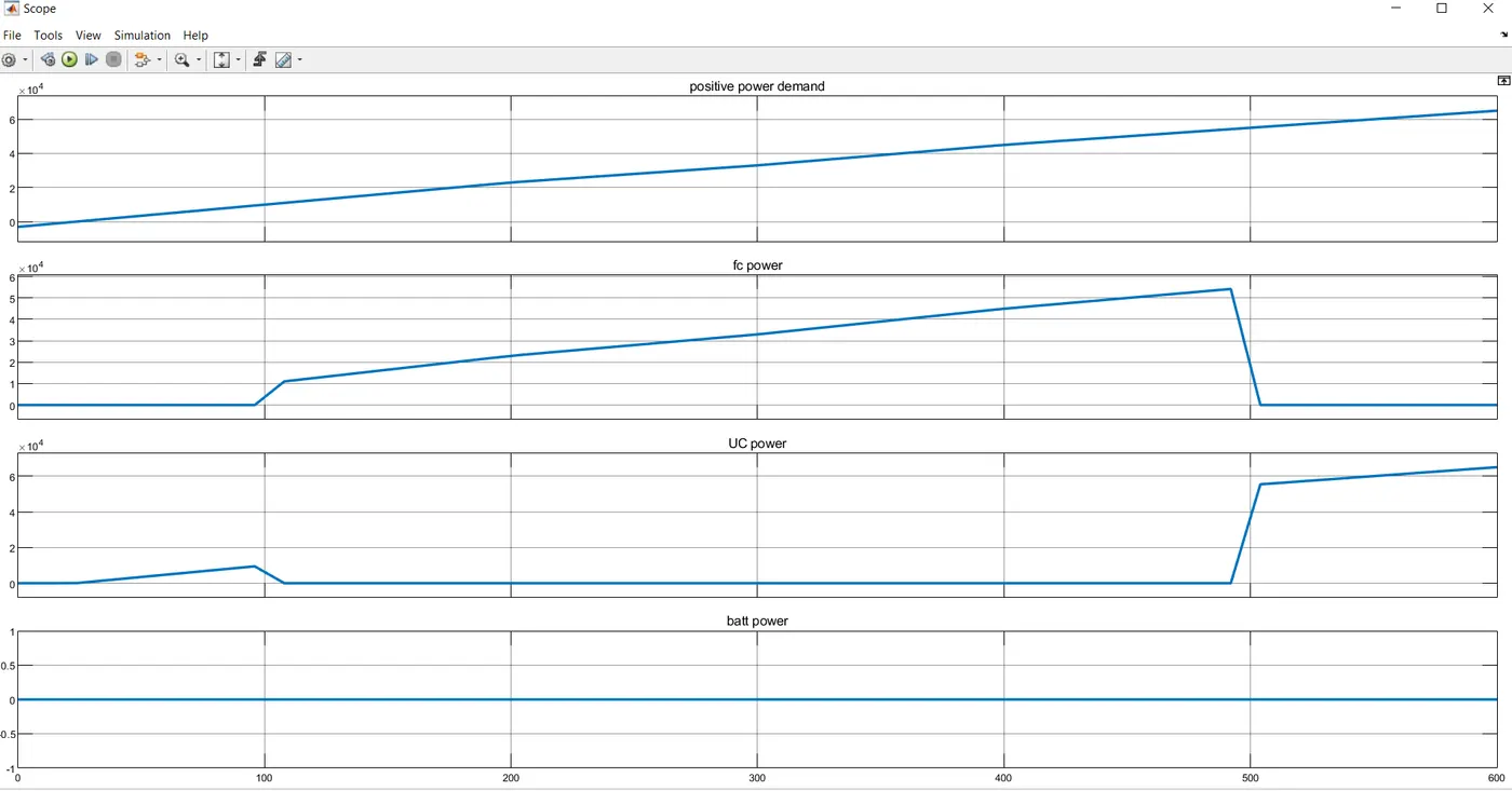
Here it is observed that as the SOC_battery=0.3 the fuel cell has covered up its energy for vehicle and the ultra capacitor is able to provide the energy for its demand.
Conclusion: The energy management strategy model with battery, UC and fuel cell for the positive power is created and corresponding characteristics are being observed.