Week-11 Challenge: Braking
Question 1:
Drive cycle:A driving cycle is a series of data points representing the speed of a vehicle versus time.
Driving cycles are produced by different countries and organizations to assess the performance of vehicles in various ways, as for instance fuel consumption, electric vehicle autonomy and polluting emissions.Fuel consumption and emission tests are performed on chassis dynamometer.Tailpipe emissions are collected and measured to indicate the performance of the vehicle.
Brake:Braking is the process of controlling the velocity of an object by inhibiting its motion. An object in motion possesses kinetic energy and to bring the object to a stop this kinetic energy must be removed. Removing the kinetic energy can be accomplished by dissipating the energy to the atmosphere through friction or by converting it into another form of energy.
The most common type of braking is a mechanical brake which inhibits motion through friction brake pads. A mechanical brake applies a friction force to convert the kinetic energy of the vehicle into thermal energy which then dissipates into the atmosphere.The consumed kinetic Energy can be derived as following equation-
Braking Energy = (1/2)*m*v^2
Where, Braking Energy is the kinetic energy in unit of Joule.
m= Total Mass of the Vehicle (Vehicle Mass + Pay Load) in unit of Kg.
v= (Initial Velocity-final Velocity) in unit m/s.
The matlab code of the barking of the vehicle for a UDDS drive cycle:
The output of the system is as follows:
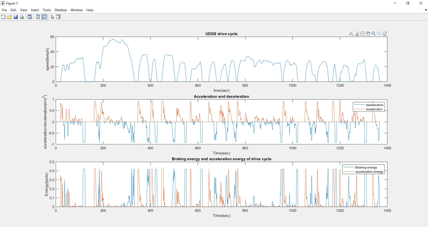
Above is the graphs related to the drive cycle and deceleration and acceleration of the vehicle. Along with them the acceleration and braking energy are also plotted.
Total brake energy =0.0553KJ
Total acceleration energy=0.0481KJ
Question 2:
Electrical and Mechanical braking: R
Regenerative braking system:A regenerative brake system (RBS) converts the kinetic energy, caused by the deceleration of the vehicle body, into another type of energy (e.g. electric, rotational kinetic) instead of dissipating it as heat through friction brakes. Brake energy recuperation is an important feature of electrified vehicles and will become increasingly important in future vehicles. In electric vehicles (EV), RBS operates as range extender and in hybrid electric vehicles (HEV) RBS significantly reduces emissions.
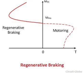
Electric motor can’t develop braking torque at high speed similar to starting, because Braking torque is applied in the opposite direction of the rotation. We can use a mechanical brake to produce a braking torque. We can also do it electrically.
Limitations of reegenrative braking :
There is a limitation due to the maximum recharging rate of the circuit and the capacity of battery, the braking force from an electromagnetic is always limited.
Independent of the RBS type, these are the main system (brake torque) limitations:
- The brake torque is not large enough to meet the requested brake torque during intensive braking. Power dissipated by a front friction brake can be above 100 [kW].
- The electric motor is unable to deliver a constant brake torque in the upper speed range. This means that the regenerative brake torque is speed dependent while the brake torque request is not.
- At speeds around zero the brake torque of the electric motor drops to zero, due to low motor electromotive force.
- At stand-still friction brakes are better to hold vehicle (parking or holding assist).
- Fail-safe function. In case the vehicle electronics malfunction the vehicle should still be able to come to a standstill, meaning a secondary brake system will be necessary. .
- RBS availability is limited by the charging condition of the energy storage system.
- By vehicle stability under critical driving (low friction or split-µ surfaces).
A Regenerative Braking system is used to convert waste energy(heat) into useful energy(stored in battery) with the help of a motor which acts as a generator when reversed. There are certain limitation with RBS i.e. the electric motor is unable to provide all the brake torque necessary for large decelerations. In case of braking if the braking torque is applied only one axle, there are chances stability and maneuverability issues can occur. So to avoid such situation regenerative braking is operated in conjunction with a friction(mechanical) brake system.
The RBS and Mechanical Brake sytem are used in strategic manner which is called as Brake Control Strategy
Series Brake Control or Series RBS:
In this type of control system the Mechanical Brakes and Regenerative(Electric) Brakes are applied one after the another. We can only apply one brake system at a time either RBS or Mechanical brakes.
The series brake system is further classified:
- Comfort of the drive
- Braking according to the energy efficiency
Parallel Brake Control or Parallel RBS:
In this type of brake control system both the Mechanical Brakes and RBS are applied simultaneously.
Question 3:
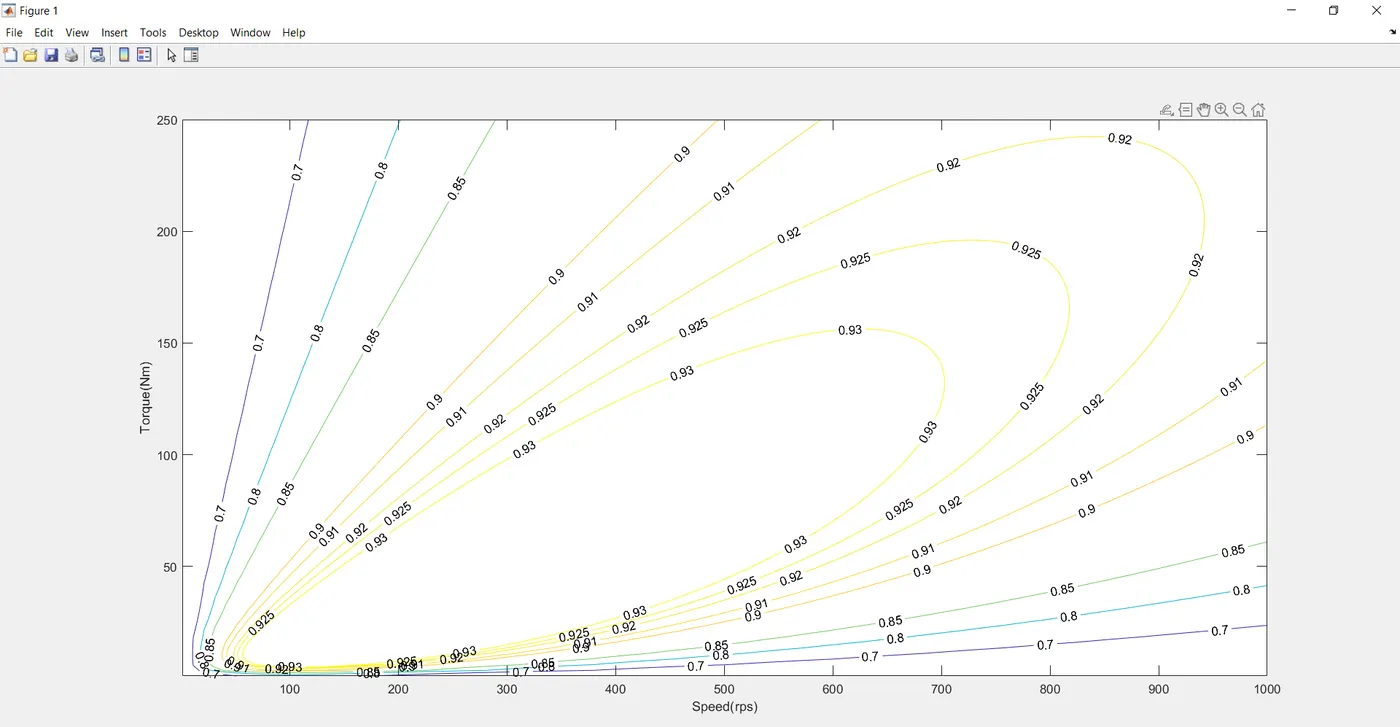
Losses that occur in all types of Electric Motor:
1. Copper Loss(I^2.R): Torque is proportional to Current; Here I = armature current and R= armature resistance
copper loss can be consider as Kc.T^2, where Kc is the resistance of brushes and the flux and its effect.
Copper Losses = Kc.T^2
2. Iron Losses: Iron losses are occured due to Magnetic losses and it is denoted as Ki.ω, where Ki is the factor which is based on the Magnetic field effect. For Permanent Magnets which has constant Magnetic field and this iron losses are based on the value of Ki and this keeps on changing due to variation in speed.
Iron Losses = Ki.ω
3. Windage Losses: This are based on the size & shape of the Motor and the amount of windage losses that the motor is going to experience.
Windage Losses = Kw.ω^3
4. Constant Losses: This losses are present in the motor constantly and are denoted by C.
Total Losses: The Total Losses are consider by combining all the four losses and denoted as,
Total Losses = Kc.T^2 + Ki.ω + Kw.ω^3 + C
The matlab code :