Project 2
Aim: To create a simultion model of the EV powertrain having fuel cell, ultracapacitor and battery as energy sources and to observe their characteristics.
Simulation model:
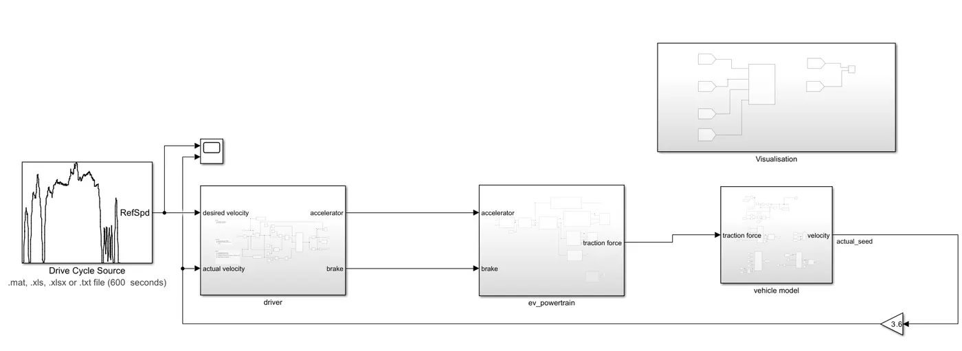
The model basically has three important blocks:
a) Driver block: Which is needed for the for the command of acceleration and brake of vehicle.
b) Electric Power train: which is needed for the energy sources mangement and providing the traction force for the vehicle.
c) Vehicle body: which describes about the vehicle parameters and environmental condition:
Drive cycle: Here, the drive cycle US06 is considered for the reference seed of the vehicle.
a) Driver block:
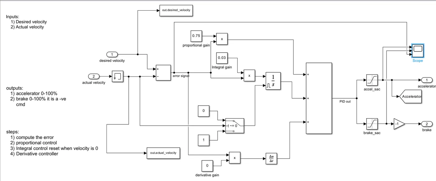
The driver block is needed for speed tracking controller. Here, the reference speed is compared with the actual speed of the vehicle and the PID controller is used to adjust the error signal and provide the acceleration and brake of the vehicle.If the output of the PID is between 0 to 1 it will be accelerator command.If the output of the PID is between -1 to 0 it will be brake command. The actual velocity is multiplied by the 3.6 to convert to m/sec
b) Electrical Powertrain block:
The electric power train block consists of the energy sources their maintainance and the power provided by them to provide the traction force needed by the vehicle. The subsystems of this block are as follows:
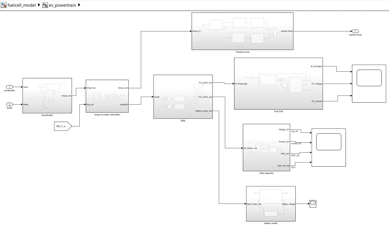
1)Accelerate or brake
2) Power calculation
3) Traction force
4)Energy Management System
5) Fuel cell, Ultra capacitor and Battery blocks for power requirements.
1) Torque requirement block:
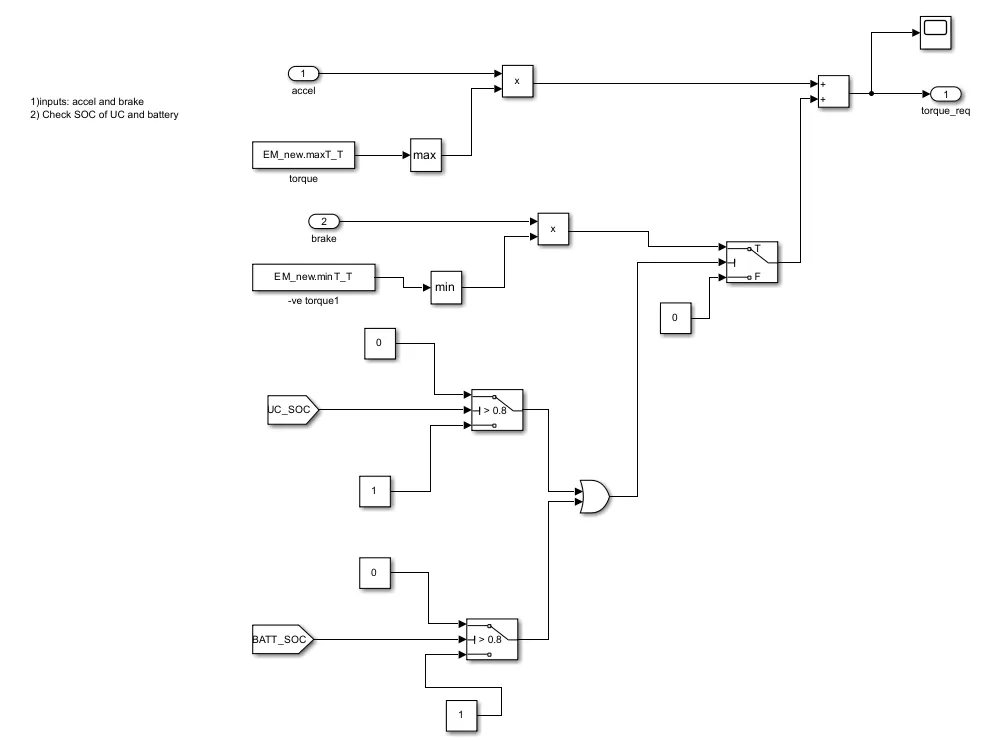
Here, the motor positive torque is taken for the acceleration of the motor and the negative torque is taken for the braking of motor. Along with torque if the UC SOC or Battery soc is greater than 80% then only the braking torque wold pass and electric braking is done.If not, the mechanical braking is done by default of the system.The summation of both torques would give the actual torque required to generate power that will deliver the tractive force to the vehicle.
2) Power calculation:
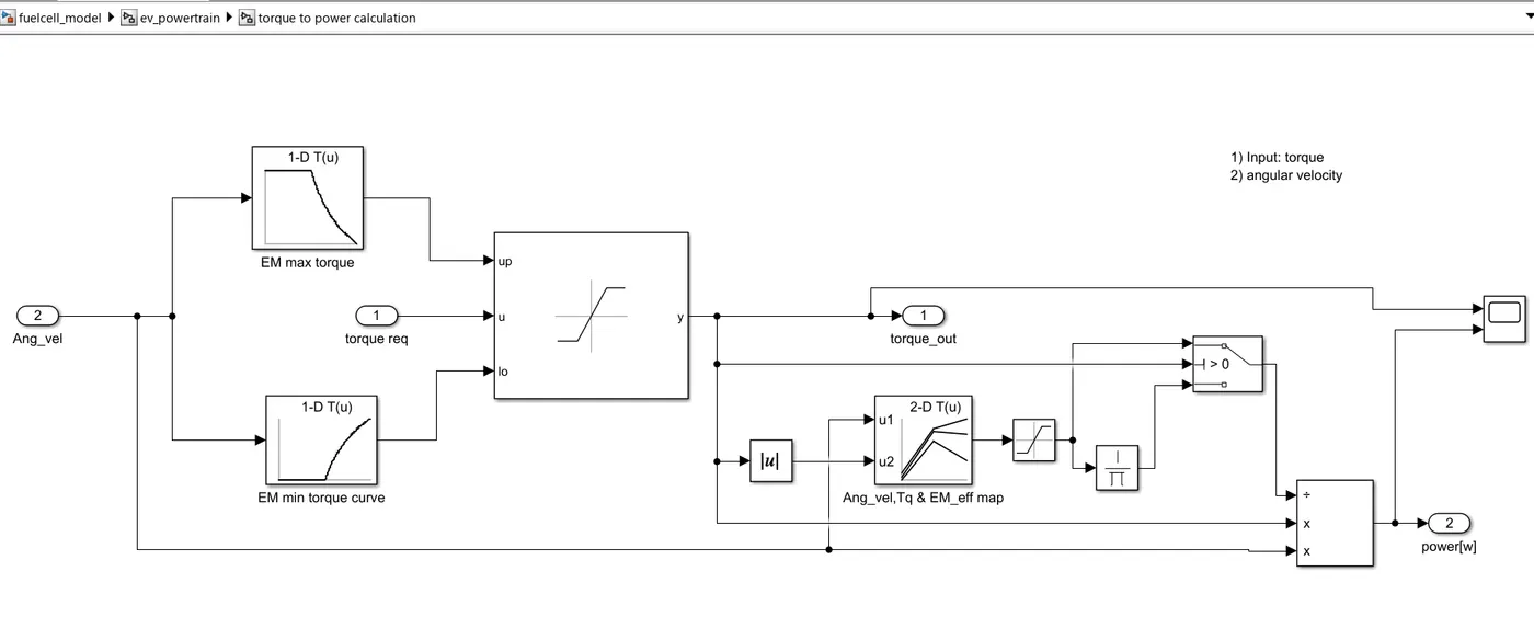
Power = Angular velocity*Torque
Here, the power would be calculated by multiplying the angular velocity acting on the front wheels and the torque from the motor with respect to the motor efficiency.
The motor accelerating and braking torques are considered and to get the motor efficiency the map of angular velocity and torque vs motor efficiency is considered.From this the torque and power demand of the system are obtained which are fed to traction force and energy management system.
3) Traction force subsystem:
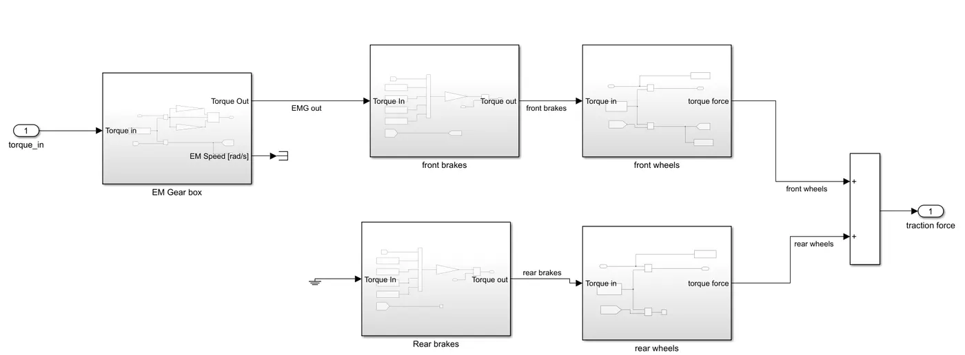
This system consists of the gearbox and the braking system of th wheels of vehicle.The subsystems in the block are as follows.
a) Gear box:
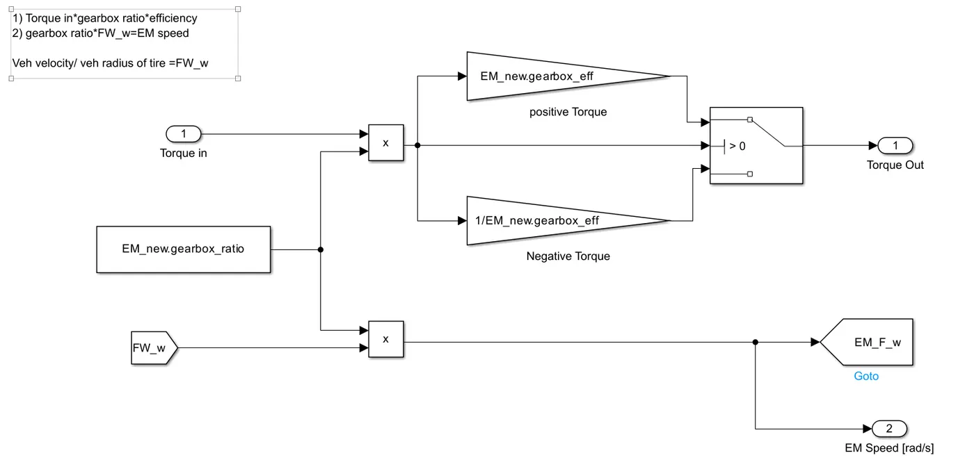
Based on the gearbox ratio and efficiency the torque and motor speed are given. The formula used in the system are as follows:
- Torque out from gearbox=Torque In x Gearbox ratio x Efficiency
- EM speed=Gearbox ratio x Angular velocity of front wheel
- Vehicle velocity/vehicle radius of tire = Angular velocity of front wheel
- Electric Motor speed in rad/sec=Gearbox ratio x Angular velocity of front wheel
b) Front brake: The torque required for the motor to apply brake on the front wheels are as follows.
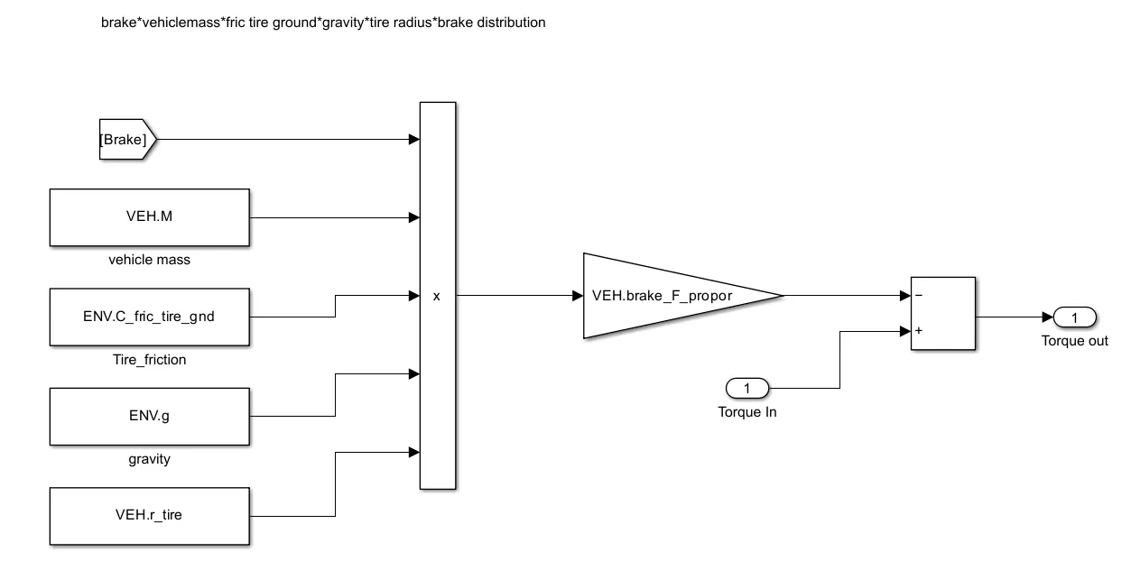
front brake torque = Brake x vehicle mass x friction tire ground x gravity x tire radius x brake distribution
c) Front wheels: The force act on the wheels are as follows:
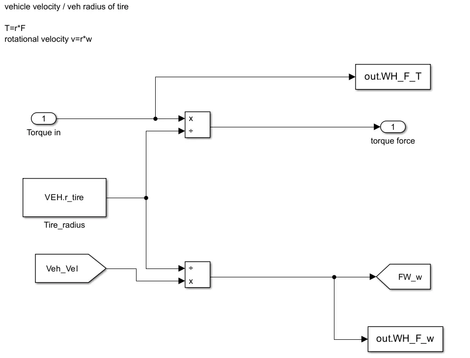
- Tractive Force = Torque/vehicle radius
- Angular velocity of front wheel=Vehicle velocity/vehicle radius of tire
d) Rear brake:The torque required for the motor to apply brake on the rear wheels are as follows.
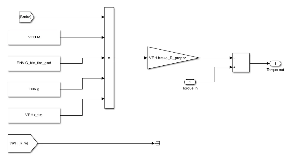
rear brake torque = Brake x vehicle mass x friction tire ground x gravity x tire radius x brake distribution
The torque input of the rear wheel is given to the ground since the vehicle running by the front axial and the angular velocity of the rear wheel is not considered it is the same as the front wheel’s angular velocity.
e)Rear wheel:The force act on the wheels are as follows:
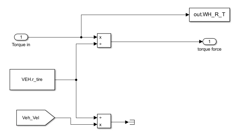
- Tractive Force = Torque/vehicle radius
- Angular velocity of front wheel=Vehicle velocity/vehicle radius of tire
4) Energy management system:
Energy management strategy (EMS) is an important link during the HEV/PHEV design procedure, which can govern the energy flow between the fuel tank and the electric energy storage by solving the energy distribution problem as well as maintaining the state of charge of the energy sources.
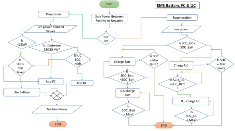
The above flowchart would describe the energy management strategy for an electrical vehicle with battery, UC and fuel cell as energy sources.
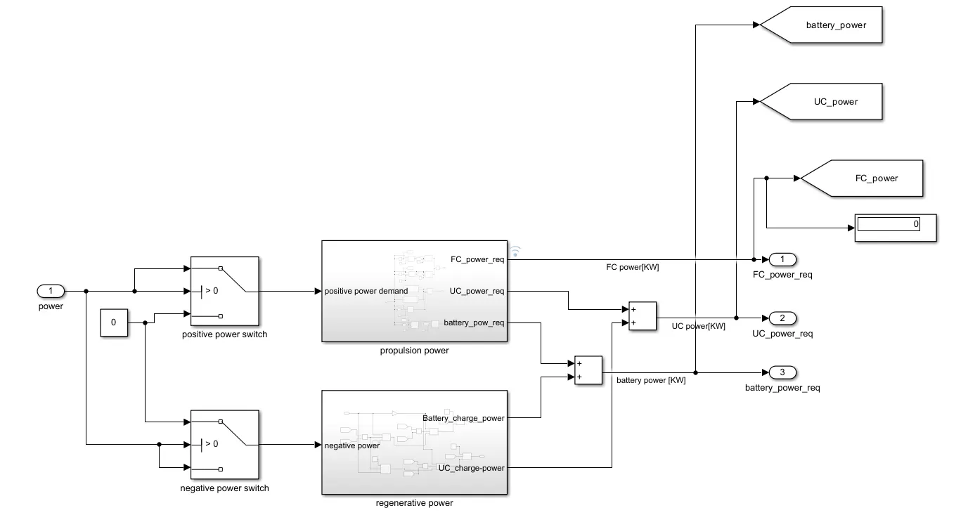
Propulsion power:
Here let us consider the corresponding power demand and the conditions for energy sources to provide energy.
| positive power demand | conditions | energy source |
| 0-9999 |
|
|
| 10000-22999 |
|
|
| 23000-54999 | No condition | Fuel cell |
| 55000 and above |
|
|
The subsystem contains the energy management of the energy sources according to the power demands and their corresonding responses are observed.
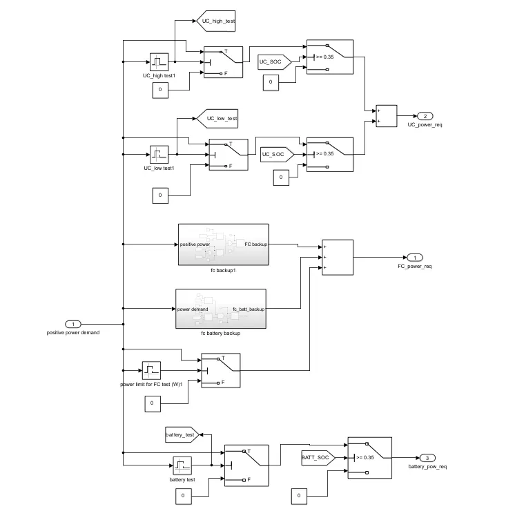
Ultracapacitor power requirement:
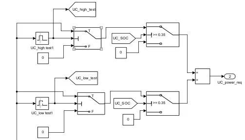
- The ultracapacitor would work in the either for high power demand or for low power demand.
- The ultracapacitor provides good performance for instantaneous power.
- In the above it is divided for the high and low power test.
- For the high power demand which is greater than 55000W and aove the UC_high_test is considered. If the power is high and the SOC of UC>0.35 then the UC would act as the power providing source.
- For the low power demand which in between 0W and 10000W the UC_low_test is considered. If the power is in between the range and the SOC of UC>0.35 then the UC would act as the power providing source.
Battery power requirement:
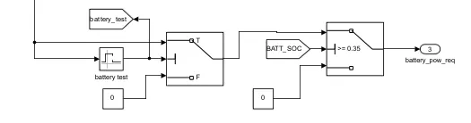
- For the low power demand the battery would be suitable.
- According to the capacity of the battery the power is given to the battery.
- Here the battery test is considered for the power demand in between 10000W to 23000W.In this battery range the battery would provide the energy if the SOC_battery>0.35.
Fuel cell power requirement:
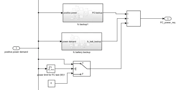
- The fuel cell would provide energy for medium range power demand.
- The fuel cell would cover up the power demand if the ultracapacitor or the battery are unable to provide the energy due to their low state of charge.
- The fuel cell would work in the power range from 23000W to 55000W.
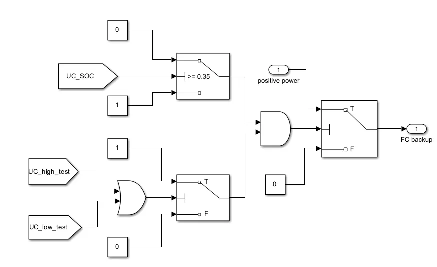
The Fuel cell would act as the backup source for the ultracapacitor when the SOC_UC<35>
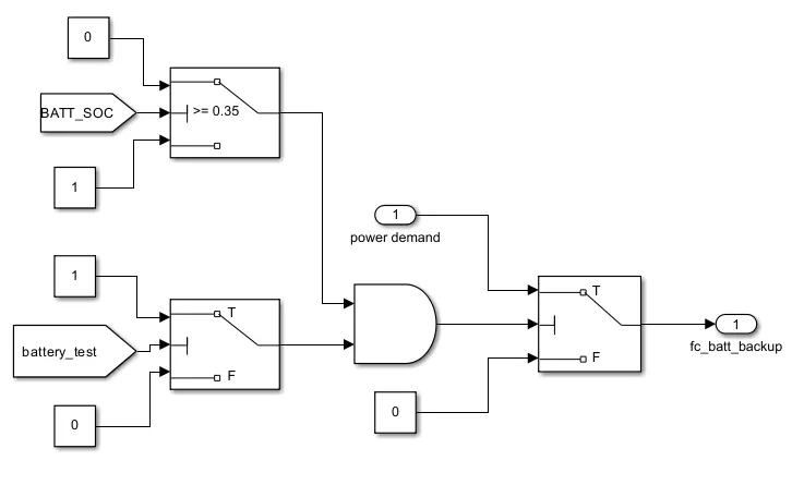
The Fuel cell would act as the backup source for the ultracapacitor when the batt_soc<35>
Regenerative power / braking power:
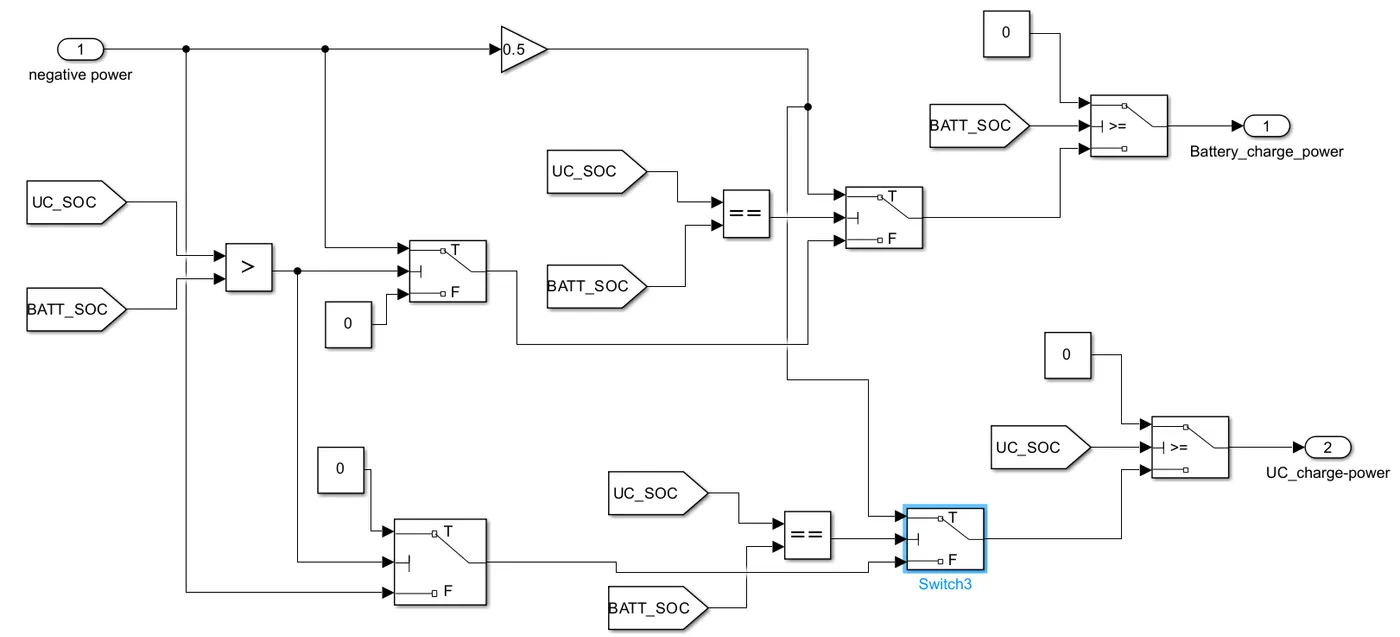
- First it would check whether UC SOC or Battery SOC is greater. If UC soc is greater then the battery would start recharging till 90% SOC. If battery SOC is greater then UC will get charged till 90% of SOC.
- If both soc are same then half of negative energy power is given to both of them and they start charging.
- The regenerative UC power and final UC propulsion power are added to get final output UC power request.
- The regenerative battery power and final battery propulsion power are added to get final output batttery power request.
- The final propulsion power as final output FC power request.
5) Fuel cell system:
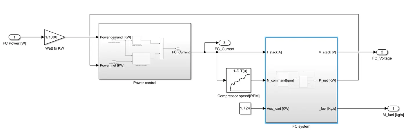
The fuel cell system consists of a Fuel cell stack that is supported by a power controller.
Fuel cell power controller:
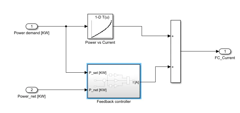
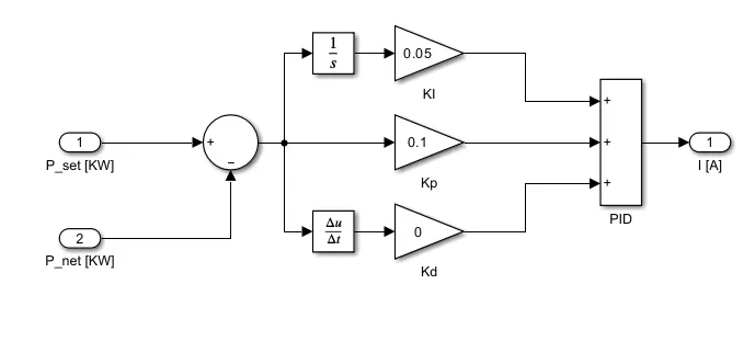
This consists of a feedback PID controller which has the reference power and net power as the input and provide the stack current to the system. To do that Power net vs Stack current OEM data need to be fed so that accordingly the power demand of the stack current will be delivered.
Fuel cell Stack system:
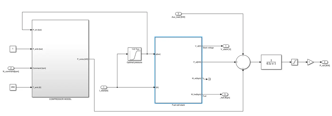
This consists of the compressor and fuel cell stack.Here, The stack current will be fed to the current vs compressor rpm so that the compressor will receive the speed command. The auxiliary load of the vehicle is also satisfied by the fuel cell system.
Compressor model:
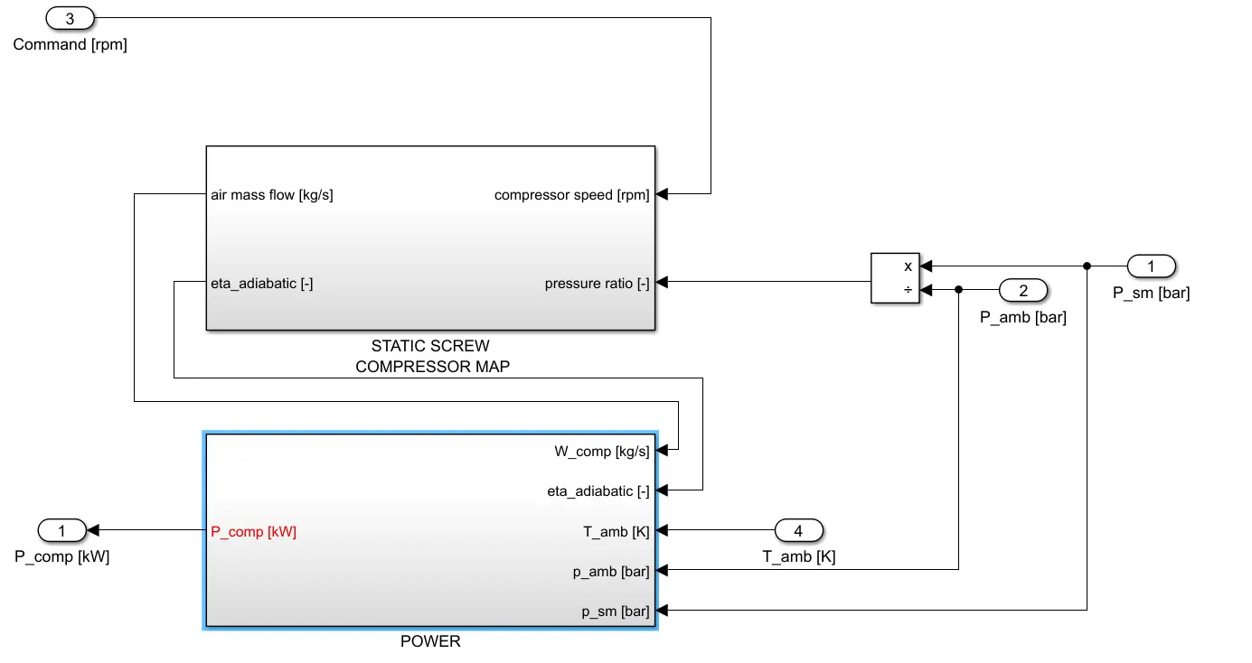
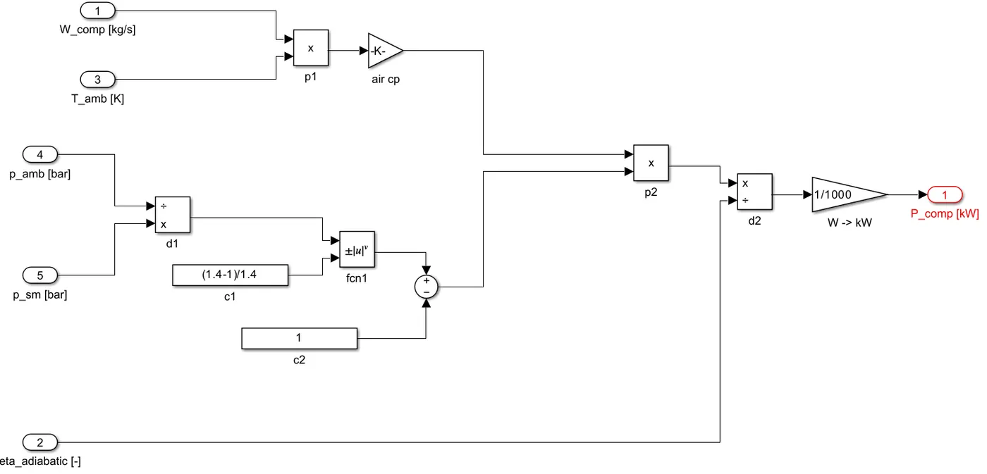
This consists of the static screw compressor along with the power need of compressor.
Static Screw Compressor map:
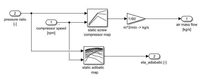
The optimal pressure divide by ambient pressure to get the pressure ratio used along with compressor speed to get the air mass flow(Kg/s) values from a 2Dlookup table .
The same inputs are used to get the eta adiabatic pressure values from a 2D lookup table.
Pressure system:
Fuel consumtion subsystem:
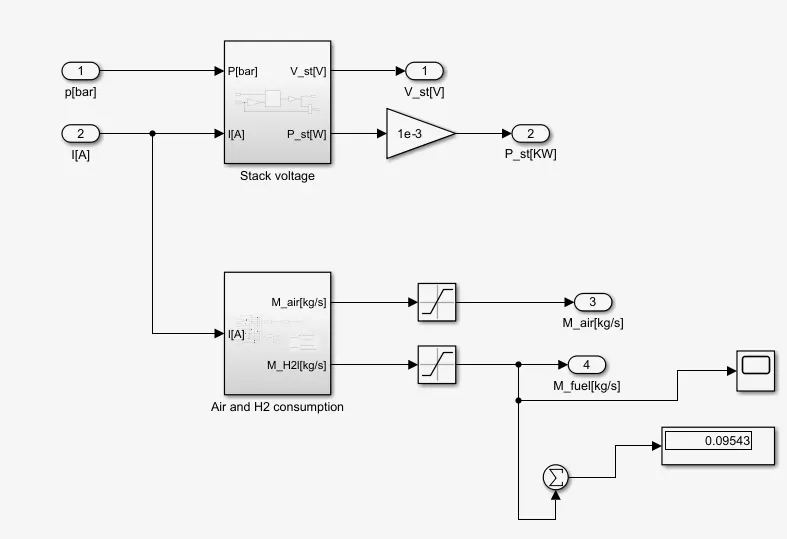
The input of the system are the power of comressor and the current and this has stack voltage and fuel consumption a the subsystem.
Stack voltage:
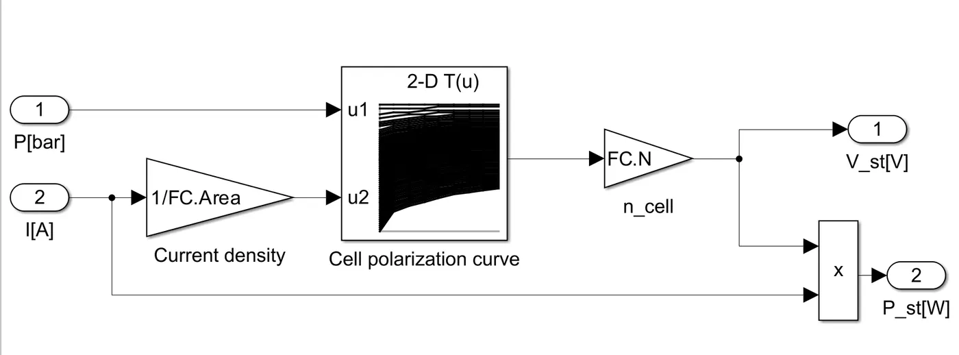
The polarization curve plays an important role in the fuel cell system.It helps for the creation of best operating point for the fuel cell to work.Using optimal pressure and current density the single FC voltage values are extracted from a 2D lookup table multiplied by number of fuel cells in series gives total output FC stack voltage. The stack current and total stack voltage multiplied to get FC stack power output.
Air and H2 Consumption:
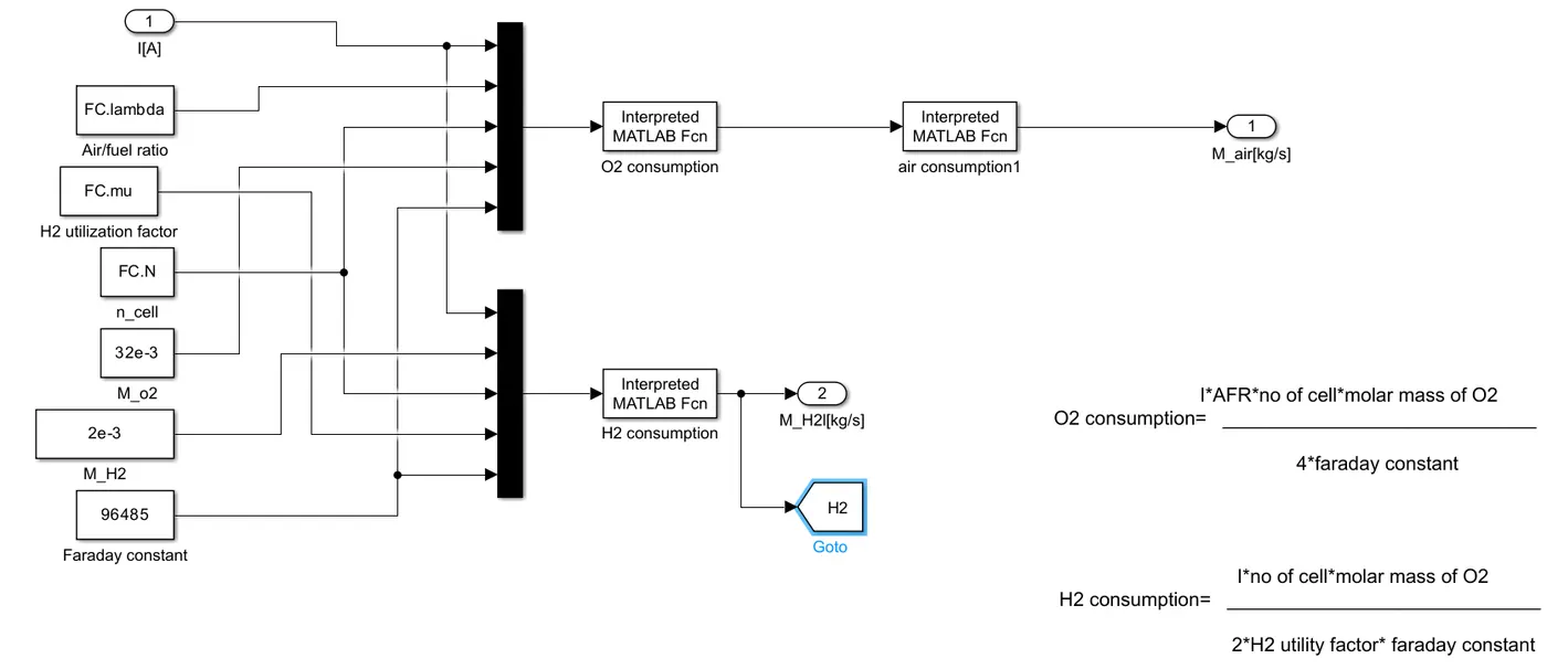
O2 consumption=(I*AFR*n_cell*molar mass of O2)/(4*Faraday constant)
H2 consumption=(I*n_cell*molar mass of H2)/(2*H2 utility factor*Faraday constant)
From these above relations this subsystem is created to get H2 and O2 consumptions values in Kg/s.From the stack power output,the compressor power and auxilary load power values are subtracted to get final net power output of fuel cell.
6) Ultracapacitor:
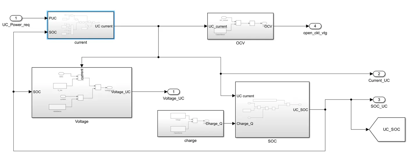
The parameters of the ultracapacitor are the subsystems. They are as follows:
1) UC current: `I=((SOC*Vmax)-(sqrt(SOC*Vmax)^2-(4*R*PUC*eff)))/(2R)`
2) UC voltage : V=(SOC*V_max)-(I*R)
3) UC OCV: `O C V = ∫ ( I /C ) d t`
4) UC charge: Q=C*V_max
5) UC SOC: `S O C = ( S O C min + S O C max 2 ) + ∫ ( (I ⋅ e f f )/Q ) d t`
7) Battery System:
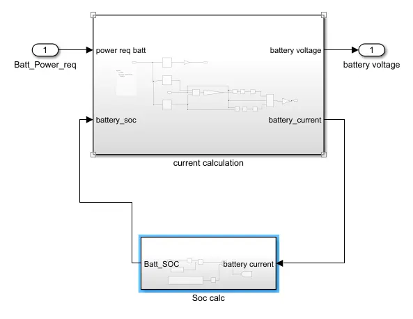
The Battery SOC can be defined as SOC(t)=SOC(t-1)+Ic(t)Qnt
To calculate the Battery voltage fed the data of battery SOC vs OCV and the resultant OCV multiplied by the no. of cells in the series of the battery pack.To calculate the Battery current, need the resistance of the battery while charging and discharging so that data of Battery SOC vs Resistance discharge and Battery SOC vs Resistance Charge is accordingly if the power demand is positive then the discharge resistance will come and calculate the discharge current else if the power demand is negative then the charge resistance will come and calculate the charge current.
c)Vehicle body:
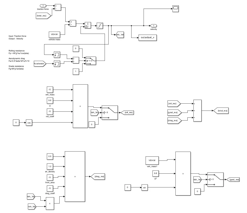
All these forces are added as shown above and subtracted from the Torque force. This resultant force is divided by the Mass to get the acceleration of the vehicle: F = M*a
- rolling resistant force Frr=Mass*g*RR*cos(Alpha)
- aero drag resistance force Faero=0.5*FA*ADcoef*Airden*(Vehicle velocity ^2)
- Hill climbing resistance force Fhc=Mass*g*RR*sin(Alpha)
Results:
The simulation time of the model is 600 sec.
Desired speed vs actual speed:
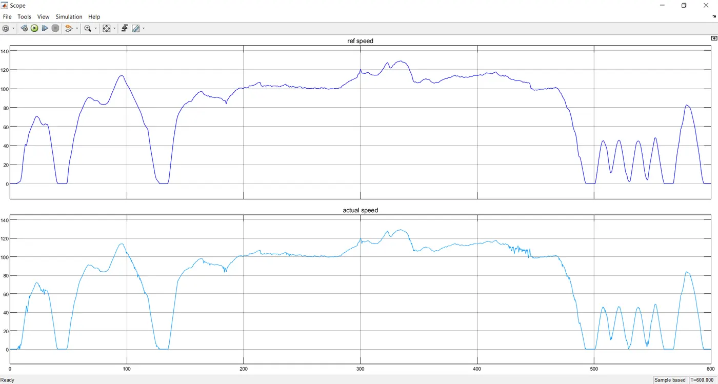
It is observed that the vehicle has achieved the desired speed of the vehicle.
Energy sources power:
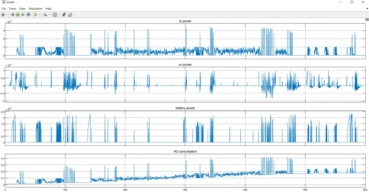
The power demand of above 55KW are acheived by the ultra capacitor.
The power demand of 0-23KW are acheived by battery.
And the power demand from above 23 KW upto 55 KW is acheived from Fuel cell.
The H2 consumption is also shown for kg/sec in the above graph. Higher the requirement of current from fuel cell higher the H2 consumption.