Final Project: Design of an Electric Vehicle
Electric vehicle Project:
Aim: To create a model of electrical car using a battery and a DC motor.
Block diagram of electric power train:
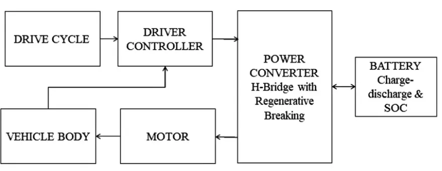
The electric vehicle consists of a battery, motor, controller, power converter, and a vehicle body. The power for the electric motor is converted from the DC Battery to AC. As the accelerator is pressed, a signal is sent to the controller. The controller adjusts the speed of the vehicle by changing the frequency of the AC power from the inverter to the motor. The motor then connects and leads to the turning of wheels through a cog. If the brakes are pressed, or the electric car is decelerating, the motor becomes an alternator and produces power, which is sent back to the battery To simulate the model, a throttle angle and a brake pedal input are given through the drive cycle. The driver controller is needed to track the particular speed of the vehicle to match the drive cycle input.
Electrical vehicles:
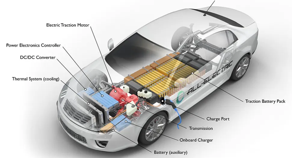
An EV is defined as a vehicle that can be powered by an electric motor that draws electricity from a battery and is capable of being charged from an external source. An EV includes both a vehicle that can only be powered by an electric motor that draws electricity from a battery (all-electric vehicle) and a vehicle that can be powered by an electric motor that draws electricity from a battery and by an internal combustion engine (plug-in hybrid electric vehicle).All-electric vehicles—also referred to as battery electric vehicles (BEVs)—plug-in hybrid electric vehicles (PHEVs), and hybrid electric vehicles (HEVs) all use electricity to improve vehicle efficiency.
- Battery electric vehicles: BEVs are also known as All-Electric Vehicles (AEV). Electric Vehicles using BEV technology run entirely on a battery-powered electric drivetrain. The electricity used to drive the vehicle is stored in a large battery pack which can be charged by plugging into the electricity grid. The charged battery pack then provides power to one or more electric motors to run the electric car.
- The main components are Electric motor, Inverter, Battery, Control Module, Drive train.
- Example is Tata Nexon EV
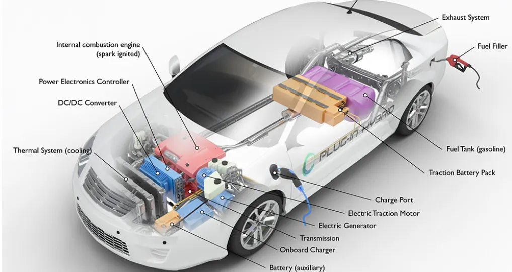
- PHEVs are powered by an internal combustion engine and an electric motor that uses energy stored in a battery. PHEVs can operate in all-electric (or charge-depleting) mode. To enable operation in all-electric mode, PHEVs require a larger battery, which can be plugged in to an electric power source to charge. To support a driver’s typical daily travel needs, most PHEVs can travel between 20 and 40 miles on electricity alone, and then will operate solely on gasoline, similar to a conventional hybrid.
- The main components are Electric motor, Engine, Inverter, Battery, Fuel tank, Control module, Battery Charger (if onboard model)
- Examples are Hyundai Sonata, Kia Optima
- HEVs:HEVs are also known as series hybrid or parallel hybrid. HEVs have both engine and electric motor. The engine gets energy from fuel, and the motor gets electricity from batteries. The transmission is rotated simultaneously by both engine and electric motor. This then drives the wheels.
- The main components are Engine, Electric motor, Battery pack with controller & inverter, Fuel tank, Control module
- Examples are Toyota pirus.
Simulation model of Electirc vehicle:
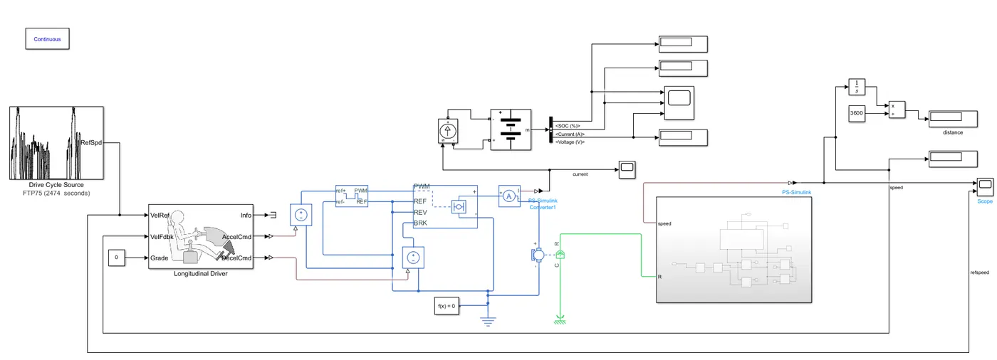
The above figure shows the ev model o this project.
Blocks:
1) Drive cycle block:It generates a standard or user-specified longitudinal drive cycle. The block output is the vehicle longitudinal speed.
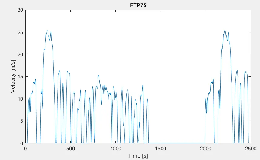
Here, for the project a drive cycle named FTP75 is considered which is there for a time period of 2474 seconds which is as follows:
2) Vehicle body:
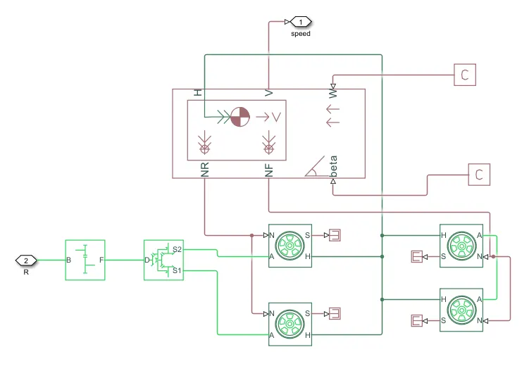
This vehicle body contains the vehicle tyres, gear box component and a vehicle body.
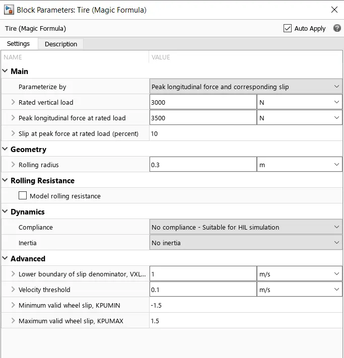
a) Tire block: The block represents the longitudinal behavior of a highway tire characterized by the tire Magic Formula. Optionally, the effects of tire inertia, compliance, and rolling resistance can be included. The effects of scaling coefficients can optionally be included when Parameterize by is Load-dependent Magic Formula coefficients or Effective rolling radius model is Load and velocity-dependent Magic Formula.
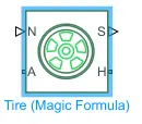
- Connection A =mechanical rotational conserving port for the wheel axle.
- Connection H = mechanical translational conserving port for the wheel hub through which the thrust developed by the tire is applied to the vehicle.
- Connection N = physical signal input port that applies the normal force acting on the tire. The force is considered positive if it acts downwards.
- Connection S = physical signal output port that reports the tire slip. Optionally expose physical signal port M by setting Parameterize by to Physical signal Magic Formula coefficients.
The parameters of the system is as follows:
b)Vehicle body:It represents a two-axle vehicle body in longitudinal motion. The block accounts for body mass, aerodynamic drag, road incline, and weight distribution between axles due to acceleration and road profile. The vehicle can have the same or a different number of wheels on each axle. Optionally include pitch and suspension dynamics or additional variable mass and inertia. The vehicle does not move vertically relative to the ground.
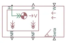
- Connection H is mechanical translational conserving port associated with the horizontal motion of the vehicle body. The resulting traction motion developed by tires should be connected to this port.
- Connections V, NF, and NR are physical signal output ports for vehicle velocity and front and rear normal wheel forces, respectively. Wheel forces are considered positive if acting downwards.
- Connections W and beta are physical signal input ports corresponding to headwind speed and road inclination angle, respectively.
The parameters of the body are as follows:
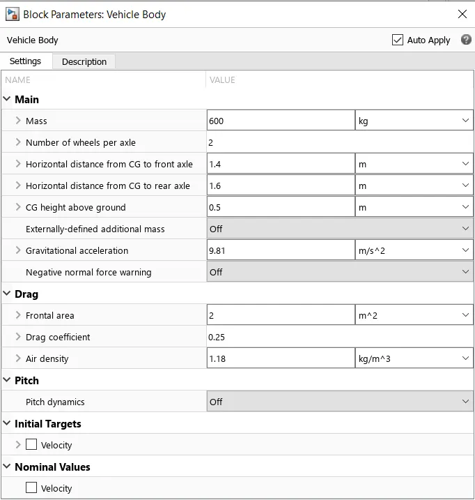
The headwind speed is taken a constant as 2 and the beta angle is considered to be zero.
c)Differential: It represents a differential which is arranged as a planetary bevel gear train equipped with an additional bevel gear transmission between the driveshaft and the carrier. The pinion gear of this transmission is attached to the driveshaft while the large bevel crown gear is affixed to the carrier. Optionally include inertia and losses from gear meshing and viscous bearing friction
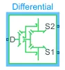
Connections D, S1, and S2 are mechanical rotational conserving ports associated with the driveshaft and the two output shafts, respectively. S1 and S2 are the shafts belonging to the two sun gears.
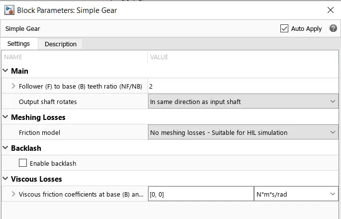
d)Simple gear: This represents a fixed-ratio gear or gear box. No inertia or compliance is modeled in this block. You can optionally include gear meshing, backlash, and viscous bearing losses.
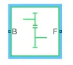
Connections B (base) and F (follower) are mechanical rotational conserving ports. Specify the relation between base and follower rotation directions with the Output shaft rotates parameter.
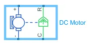
3) DC Motor block:This block represents the electrical and torque characteristics of a DC motor.
The block assumes that no electromagnetic energy is lost, and hence the back-emf and torque constants have the same numerical value when in SI units. Motor parameters can either be specified directly, or derived from no-load speed and stall torque. If no information is available on armature inductance, this parameter can be set to some small non-zero value.When a positive current flows from the electrical + to - ports, a positive torque acts from the mechanical C to R ports. Motor torque direction can be changed by altering the sign of the back-emf or torque constants.
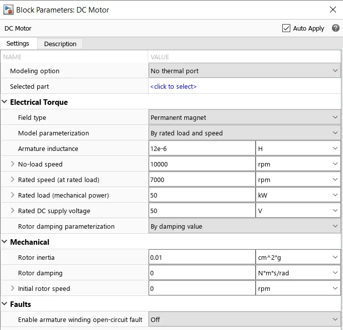
The parameters of the dc motor are as follows:
4) Battery system :
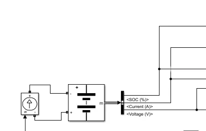
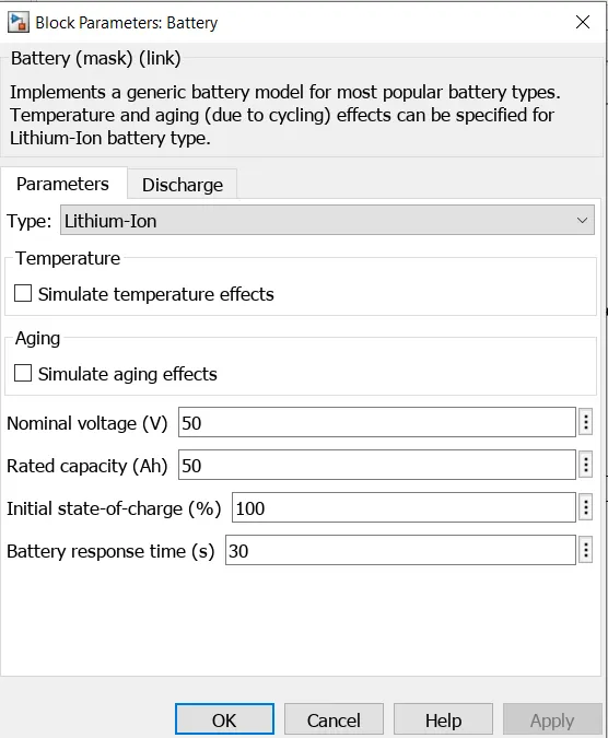
a)Battery block: It implements a generic battery model for most popular battery types. Temperature and aging (due to cycling) effects can be specified for Lithium-Ion battery type.
b)Current controlled source:Converts the Simulink input signal into an equivalent current source. The generated current is driven by the input signal of the block.
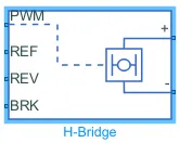
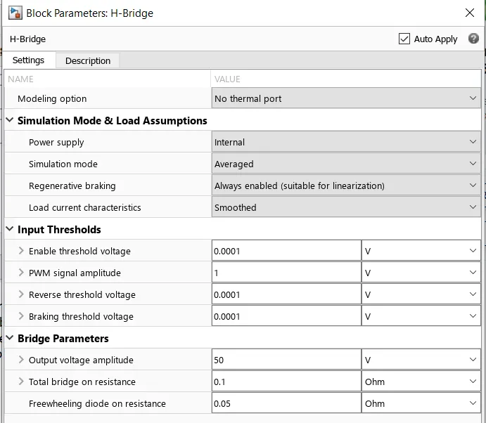
4) H-bridge converter: The block can be driven by the Controlled PWM Voltage block in PWM or Averaged mode. In PWM mode, the motor is powered if the PWM port voltage is above the Enable threshold voltage. In Averaged mode, the PWM port voltage divided by the PWM signal amplitude parameter defines the ratio of the on-time to the PWM period. Using this ratio and assumptions about the load, the block applies an average voltage to the load that achieves the correct average load current.
The parameters of the H bridge converter is as follows
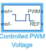
5) Controlled PWM converter:This block creates a Pulse-Width Modulated (PWM) voltage across the PWM and REF ports. The output voltage is zero when the pulse is low, and is equal to the Output voltage amplitude parameter when high. Duty cycle is set by the input value.
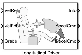
6) Longitudinal Driver: A parametric longitudinal speed tracking controller for generating normalized acceleration and braking commands based on reference and feedback velocities.
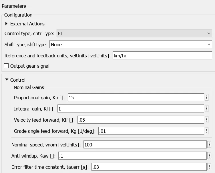
The parameters are as follows:
Results:
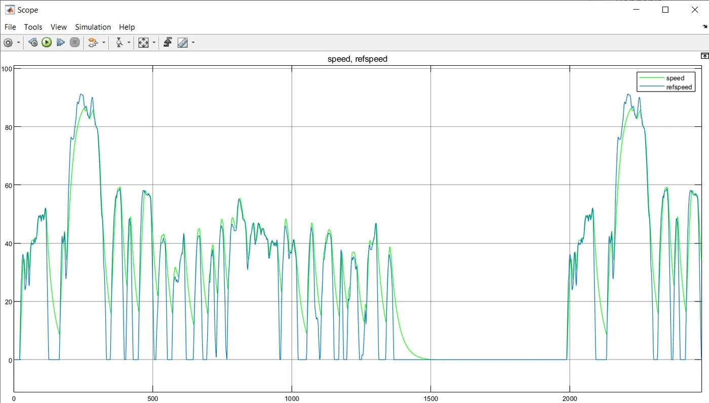
The above graph depicts the reference speed(drive cycle) and actua speed of the vehicle that is followed.
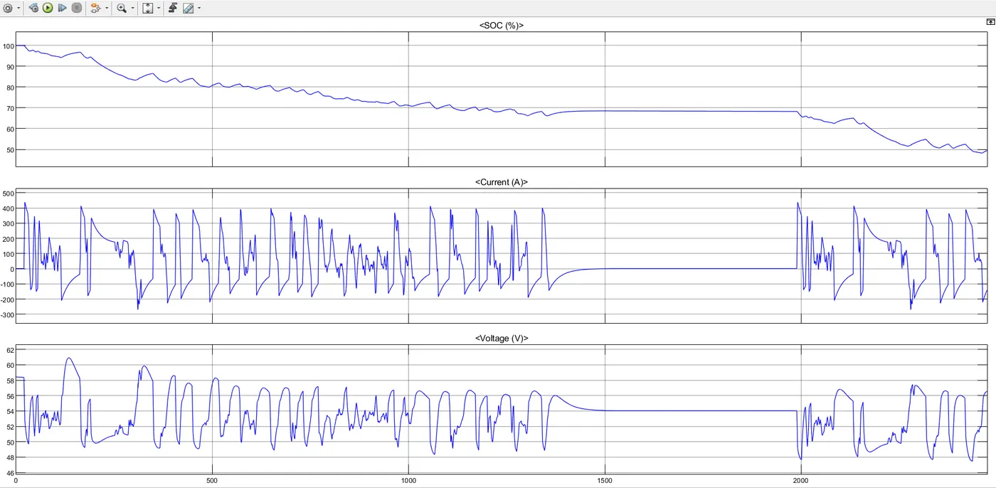
The above garph shows the SOC current and voltage of the battery.
The SOC % is managed to be from 100 to 49%.
The graph of current and voltage is being fluctuated in the responce to the driving of the vehicle.
The vehicle has travelled a distance of 20.77kmph.
Conclusion:
The electrical vehicle model has been created using matlab simulink.The model had inut as Drive cycle source (FTP575(2474sec)) the simulation has produced the results of vehicle velocity with respect to acceleration and the current flowing state of charge as well as the distance travelled in simulation time. The vehicle travelled to a distance of 20.77 in 2474 sec with 49% of SOC.
The DC motor is used to run the Rear axel of the vehicle and when the car is with no load condition then the motor operating RPM is 10000 and when the car is running at some load or we can say that some rated speed then the motor RPM is taken as 7000. The voltage supply to DC motor is 50 V.