Simulating Incompressible Laminar Viscous Flow through Backward facing step in OpenFOAM
AIM: To simulate incompressible laminar viscous flow through the backward-facing step geometry.
Introduction: In this challenge, the flow-through backward-facing step has been simulated using icoFOAM solver which is performed in OpenFOAM software. As a result, if the simulation, velocity, pressure profile for different mesh grading factors can be achieved. The dimensions of a given backward-facing step are below. And simulate the flow with different garding factors.
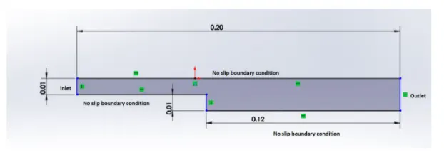
Nature of flow: Incompressible flow
Block Mesh specification:
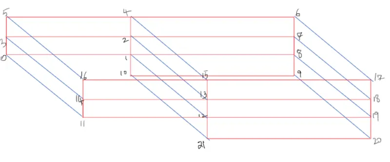
Number of blocks = 5
The arrangement of blocks is as follow:

To understand it more clearly take a look at the figure below:
Mesh Specification:
- Number of cells along the X-direction(longer dimension) = 200
- Number of cells along with the y-direction = 10
Desired Output:
- Run the first simulation without grading factor
- Run the second simulation with a mesh grading factor of 0.2, 0.5, 0.8. Compare the effect of grading factor with necessary contour & plots.
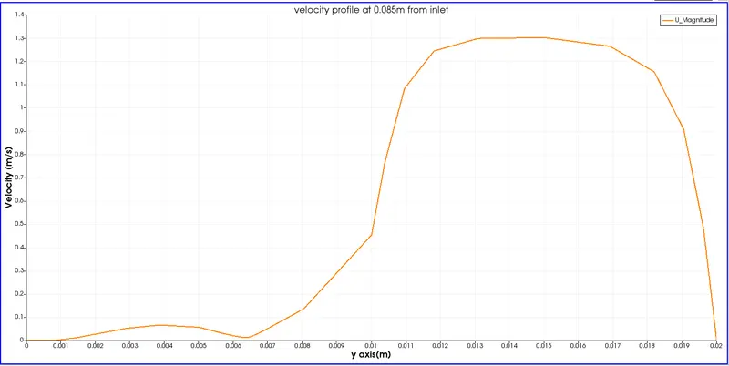
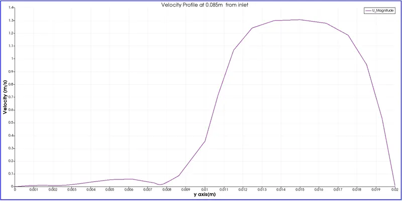
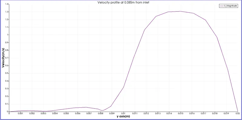
- Measure the velocity profile at 0.085m from the inlet of the geometry with a line plot.
- Compare velocity magnitude contour near the step region for the above-mentioned grading factors.
OpenFoam Code for creating given geometry using BlockMesh
/*--------------------------------*- C++ -*----------------------------------*
  =========                 |
        /  F ield         | OpenFOAM: The Open Source CFD Toolbox
       /   O peration     | Website:  https://openfoam.org
      /    A nd           | Version:  8
     /     M anipulation  |
*---------------------------------------------------------------------------*/
FoamFile
{
    version     2.0;
    format      ascii;
    class       dictionary;
    object      blockMeshDict;
}
// * * * * * * * * * * * * * * * * * * * * * * * * * * * * * * * * * * * * * //

convertToMeters 1;

vertices
(
    (0 0 0) //0
    (0.08 0 0) //1
    (0.08 0.005 0) //2
    (0 0.005 0)  //3
    (0.08 0.01 0)  //4
    (0 0.01 0)  //5
    (0.2 0.01 0)  //6
    (0.2 0.005 0)  //7
    (0.2 0 0) //8
    (0.2 -0.01 0) //9
    (0.08 -0.01 0) //10

    (0 0 0.001)  //11
    (0.08 0 0.001)  //12
    (0.08 0.005 0.001)  //13
    (0 0.005 0.001)  //14
    (0.08 0.01 0.001)  //15
    (0 0.01 0.001)  //16
    (0.2 0.01 0.001)  //17
    (0.2 0.005 0.001)  //18
    (0.2 0 0.001)  //19
    (0.2 -0.01 0.001)  //20
    (0.08 -0.01 0.001) // 21
);
blocks
(
    hex (0 1 2 3 11 12 13 14) (80 5 1) simpleGrading (0.2 5 1)
    hex (3 2 4 5 14 13 15 16) (80 5 1) simpleGrading (0.2 0.2 1)
    hex (2 7 6 4 13 18 17 15) (120 5 1) simpleGrading (5 0.2 1)
    hex (1 8 7 2 12 19 18 13) (120 5 1) simpleGrading (5 5 1)
    hex (10 9 8 1 21 20 19 12) (120 10 1) simpleGrading (5 5 1)
);

edges
(
);

boundary
(
    inlet
    {
        type patch;
        faces
        (
            (0 11 14 3)
            (3 14 16 5)
        );
    }
    outlet
    {
    	type patch;
    	faces
    	(
    		(9 8 19 20)
    		(8 7 18 19)
    		(7 6 17 18)
    	);

    }
    upperwalls
    {
    	type wall;
    	faces
    	(

    		(5 16 15 4)
    		(4 15 17 6)

    	);

    }
    lowerwalls
    {
    	type wall;
    	faces
    	(
    		(0 1 12 11)
    		(10 9 20 21)
    		(10 21 12 1)

    	);

    }
    frontAndBack
    {
        type empty;
        faces
        (
            (3 2 1 0)
            (5 4 2 3)
            (4 6 7 2)
            (2 7 8 1)
            (1 8 9 10)
            (11 12 13 14)
            (14 13 15 16)
            (13 18 17 15)
            (12 19 18 13)
            (21 20 19 12)

        );
    }
 );
mergePatchPairs
(
);


// ************************************************************************* //
Inlet, outlet, upper wall, lower wall, front, and back are user-defined faces for creating boundary conditions in the above code.
Time-step Definition:
Run time t= 50 s
Time-step size dt = 0.0005 s
/*--------------------------------*- C++ -*----------------------------------*
  =========                 |
        /  F ield         | OpenFOAM: The Open Source CFD Toolbox
       /   O peration     | Website:  https://openfoam.org
      /    A nd           | Version:  8
     /     M anipulation  |
*---------------------------------------------------------------------------*/
FoamFile
{
    version     2.0;
    format      ascii;
    class       dictionary;
    location    "system";
    object      controlDict;
}
// * * * * * * * * * * * * * * * * * * * * * * * * * * * * * * * * * * * * * //

application     icoFoam;

startFrom       startTime;

startTime       0;

stopAt          endTime;

endTime         0.5;

deltaT          0.0005;

writeControl    timeStep;

writeInterval   20;

purgeWrite      0;

writeFormat     ascii;

writePrecision  6;

writeCompression off;

timeFormat      general;

timePrecision   6;

runTimeModifiable true;


// ************************************************************************* //
Boundary Conditions
Velocity for user-defined faces.
/*--------------------------------*- C++ -*----------------------------------*
  =========                 |
        /  F ield         | OpenFOAM: The Open Source CFD Toolbox
       /   O peration     | Website:  https://openfoam.org
      /    A nd           | Version:  8
     /     M anipulation  |
*---------------------------------------------------------------------------*/
FoamFile
{
    version     2.0;
    format      ascii;
    class       volVectorField;
    object      U;
}
// * * * * * * * * * * * * * * * * * * * * * * * * * * * * * * * * * * * * * //

dimensions      [0 1 -1 0 0 0 0];

internalField   uniform (0 0 0);

boundaryField
{
    inlet
    {
        type            fixedValue;
        value           uniform (1 0 0);
    }

    outlet
    {
        type            zeroGradient;
    }
    upperwalls
    {
    	type		noSlip;
    }

    lowerwalls
    {
    	type		noSlip;
    }

    frontAndBack
    {
        type            empty;
    }

}

// ************************************************************************* //
Pressure for user-defined faces.
/*--------------------------------*- C++ -*----------------------------------*
  =========                 |
        /  F ield         | OpenFOAM: The Open Source CFD Toolbox
       /   O peration     | Website:  https://openfoam.org
      /    A nd           | Version:  8
     /     M anipulation  |
*---------------------------------------------------------------------------*/
FoamFile
{
    version     2.0;
    format      ascii;
    class       volScalarField;
    object      p;
}
// * * * * * * * * * * * * * * * * * * * * * * * * * * * * * * * * * * * * * //

dimensions      [0 2 -2 0 0 0 0];

internalField   uniform 0;

boundaryField
{
    inlet
    {
        type            zeroGradient;
    }

    outlet
    {
        type            fixedValue;
        value		 uniform 0;
    }
    upperwalls
    {
    	type		 zeroGradient;

    }

    lowerwalls
    {
    	type		 zeroGradient;

    }

    frontAndBack
    {
        type            empty;
    }
 }

// ************************************************************************* //
Kinematic viscosity of working fluid(Air) = 1.48e-5 `m^2/s`
/*--------------------------------*- C++ -*----------------------------------*
  =========                 |
        /  F ield         | OpenFOAM: The Open Source CFD Toolbox
       /   O peration     | Website:  https://openfoam.org
      /    A nd           | Version:  8
     /     M anipulation  |
*---------------------------------------------------------------------------*/
FoamFile
{
    version     2.0;
    format      ascii;
    class       dictionary;
    location    "constant";
    object      transportProperties;
}
// * * * * * * * * * * * * * * * * * * * * * * * * * * * * * * * * * * * * * //

nu              [0 2 -1 0 0 0 0] 1.48e-5;


// ************************************************************************* //
Mesh Grading Factor(MGF)
It is used to stretch the mesh in a particular axis. For our challenge, we are using 0.2, 0.5, and 0.8 as our grading factors.
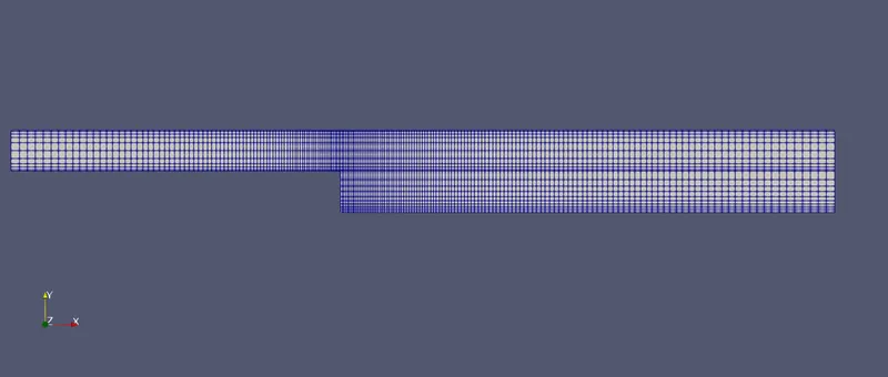
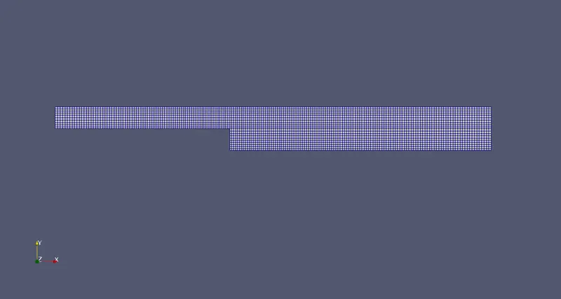
OpenFoam Code for creating the mesh with MGF =0.2
blocks
(
    hex (0 1 2 3 11 12 13 14) (80 5 1) simpleGrading (0.2 5 1)
    hex (3 2 4 5 14 13 15 16) (80 5 1) simpleGrading (0.2 0.2 1)
    hex (2 7 6 4 13 18 17 15) (120 5 1) simpleGrading (5 0.2 1)
    hex (1 8 7 2 12 19 18 13) (120 5 1) simpleGrading (5 5 1)
    hex (10 9 8 1 21 20 19 12) (120 10 1) simpleGrading (5 5 1)
);
The geometry after meshing,
OpenFoam code for creating mesh with MGF = 0.5
blocks
(
    hex (0 1 2 3 11 12 13 14) (80 5 1) simpleGrading (0.5 2 1)
    hex (3 2 4 5 14 13 15 16) (80 5 1) simpleGrading (0.5 0.5 1)
    hex (2 7 6 4 13 18 17 15) (120 5 1) simpleGrading (2 0.5 1)
    hex (1 8 7 2 12 19 18 13) (120 5 1) simpleGrading (2 2 1)
    hex (10 9 8 1 21 20 19 12) (120 10 1) simpleGrading (2 2 1)
);
The geometry after meshing
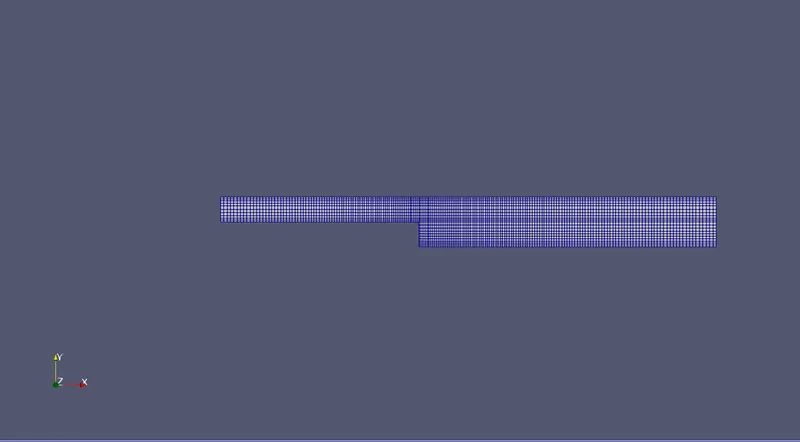
OpenFoam code for creating mesh with MGF= 0.8
blocks
(
    hex (0 1 2 3 11 12 13 14) (80 5 1) simpleGrading (0.8 1.25 1)
    hex (3 2 4 5 14 13 15 16) (80 5 1) simpleGrading (0.8 0.8 1)
    hex (2 7 6 4 13 18 17 15) (120 5 1) simpleGrading (1.25 0.8 1)
    hex (1 8 7 2 12 19 18 13) (120 5 1) simpleGrading (1.25 1.25 1)
    hex (10 9 8 1 21 20 19 12) (120 10 1) simpleGrading (1.25 1.25 1)
);
Geometry after meshing
Results
- Velocity profile for MGF =0.2
- Velocity profile for MGF =0.5
- Velocity profile for MGF =0.8
- Animation of flow through backward-facing step(MGF = 0.2)
- Animation of flow through backward-facing step(MGF = 0.5)
- Animation of flow through backward-facing step(MGF = 0.8)
Conclusion:
- By calculating the Mesh Grading factor, flow quantities can be calculated at the desired location. In our simulation flow quantities are calculated in more numbers of grid near to all walls.
- From the above graph, it was noted that the velocity profile gets smoother near the walls. In MGF = 0.2 velocity profile is smoother near the wall as compared to other MGF.
- But in MGF = 0.2 velocity profile has some sharp edges in the region other than the wall. Because of the coarse mesh in this region, MGF = 0.5 & 0.8 have smooth curves.