Week 8 - Challenge 5 - Core & Cavity Design
BEZEL SWITCH - CORE AND CAVITY DESIGN
Introduction
Parting Surface
When designing a plastic injection mold, the selection of the parting surface is an important design factor. With a reasonable parting surface selection, the mold structure can be simpler, making it easier to mold and release the plastic product, with product quality guaranteed. If the parting surface is inappropriately selected, mold structure becomes complex, making it difficult to mold the plastic product, thus affecting product quality. Therefore, the selection of the parting surface is of great importance to the design of mold structure.
The parting surface of a mould are those surfaces of both mould plates adjacent to the impressions which butt together to form a seal and prevent the loss of plastic material from the impression.
Parting Line
A ‘parting line’ is the line of separation on the plastic part where the two halves of the plastic injection mold meet. The line actually indicates the parting ‘plane’ that passes through the part. Within more basic plastic part design plans this plane can be a simple, flat surface, but it is often a complex form that traces the perimeter of the part around the various features that make up the part’s outer ‘silhouette’.
Process
Draft Analysis of Bezel Switch
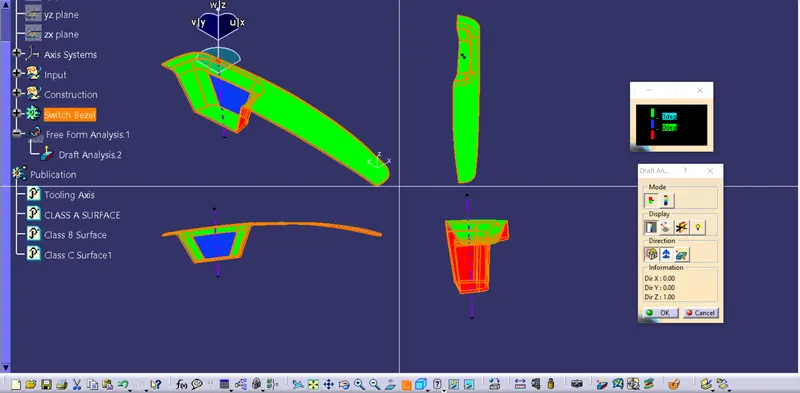
- Faces in green have a draft angle of 3 degrees or more
- The faces which have draft angle below 3 degree but greater than 0 degree are in blue
- Those with negative draft angle are in red
Core and Cavity Design
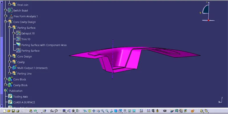
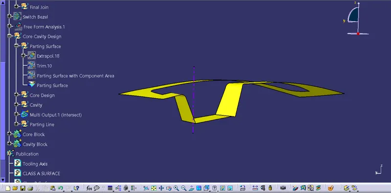
1. Parting Surface
- The class A surface is extrapolated and trimmed with the class C surface
- This trimmed surface is again trimmed with the B surface, this becomes the Parting surface with the component area and this surface is used to create the core and cavity
- The C and A surface that were trimmed with each other are split with the B surface, removing the Bezel Switch area, and this surface is known as the Parting Surface
Parting surface with component area
Parting Surface
2. Core Design
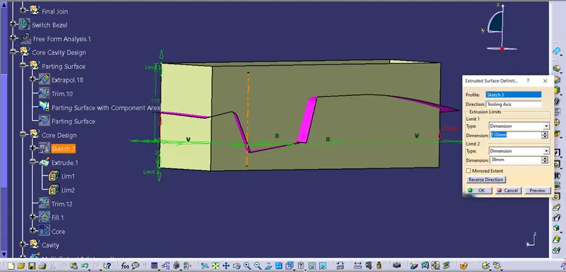
- A rectangle is drawn on XY plane which is parallel to the Bezel surface
- This recangle defines the area covered by the core and also cavity
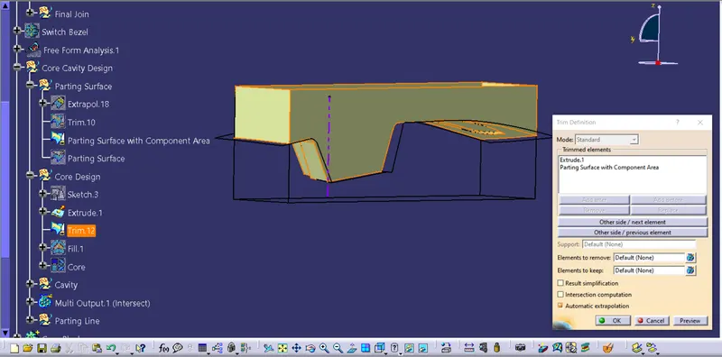
- The sketch is extruded along the tooling axis and then trimmed with the parting surface with the component area
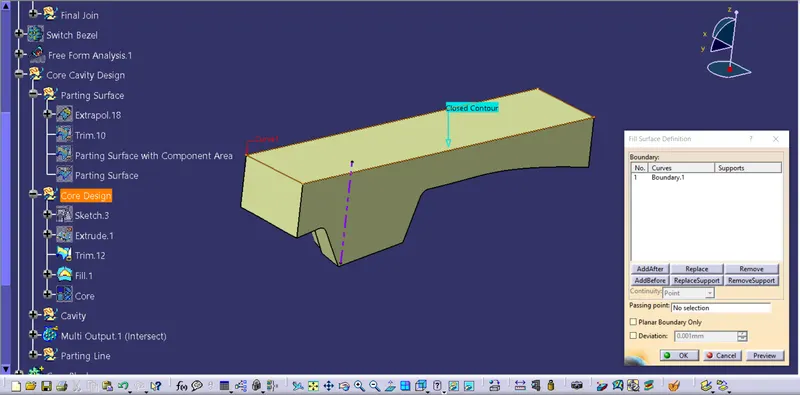
- The trimmed surface is then closed using the Fill command and then joined to for a closed surface body
- This surface is then turned to a closed plastic body
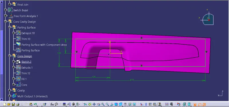
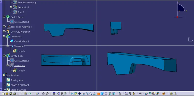
Core
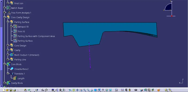
Views of the Core
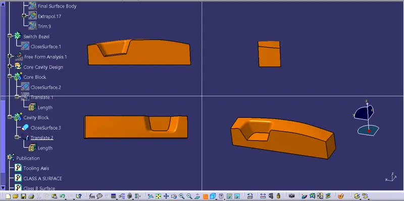
3. Cavity Design
- The retangle sketched in the YX plane is again extruded along the tooling axis
- The extrude is trimmed with the B surface and the surface is closed using Fill command
- This surface body is converted to the closed pastic body
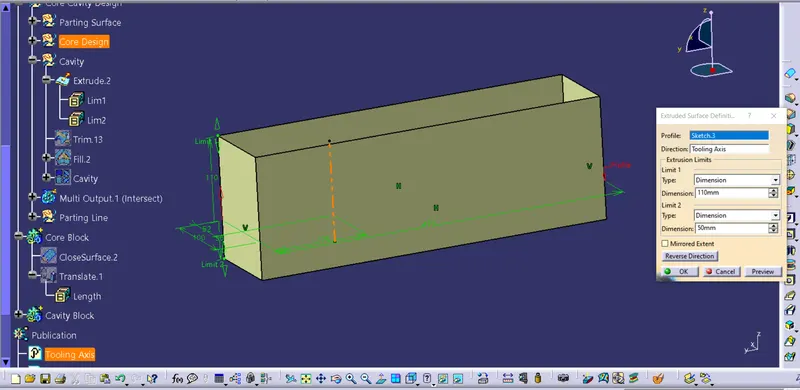
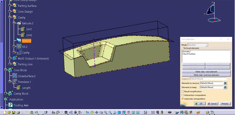
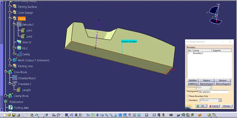
Cavity
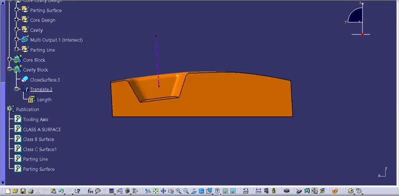
Views of the Cavity
4. Parting Line
- The class C surface joined with the A surface is intersected with the B surface
- This intersected line is the Parting Line
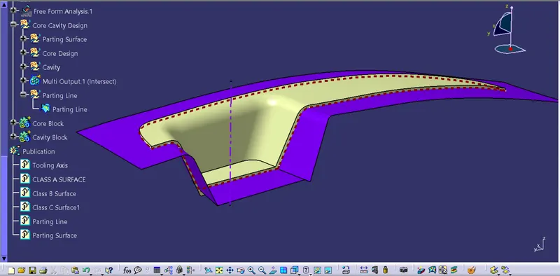
Core and Cavity with the component, parting surface and line
Conclusion
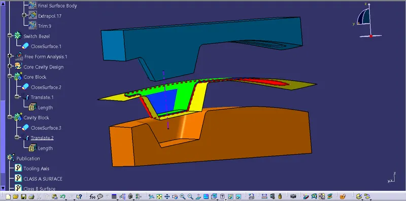
Thus, we successfully designed the Core, Cavity, Parting surface and Parting line for the Bezel Switch.