Advanced Sheet Metal Design Using NX Cad Challenge_2_Box Assembly
BOX ASSEMBLY DESIGN using NX-CAD
Objective
Learning to design a sheet metal Box Assembly in NX-CAD
Introduction
Sheet metal is metal formed by an industrial process into thin, flat pieces. Sheet metal is one of the fundamental forms used in metalworking, and it can be cut and bent into a variety of shapes. Countless everyday objects are fabricated from sheet metal. Thicknesses can vary significantly; extremely thin sheets are considered foil or leaf, and pieces thicker than 6 mm (0.25 in) are considered plate steel or "structural steel".
Here we would be designing a Box Assembly from sheet metal in NX-CAD
Design methodology / approach
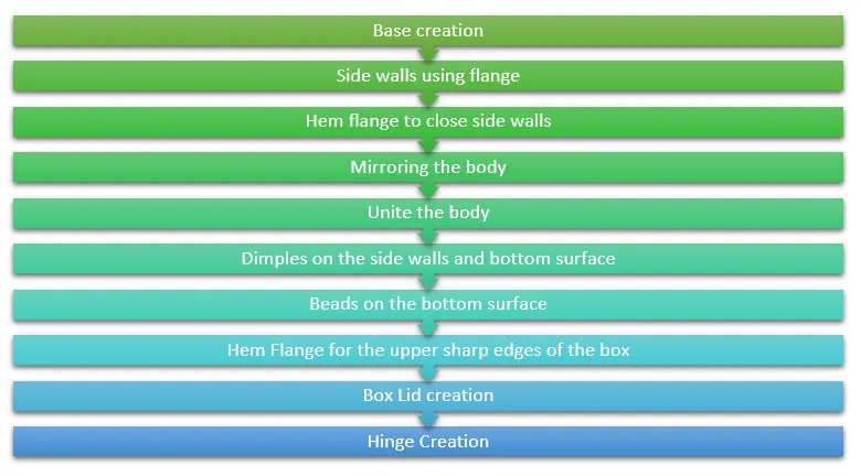
Model design description
The Box Assembly is made in 3 parts
- Box
- Lid
- Hinge
The method of designing the above mentions parts is given below.
1. Box
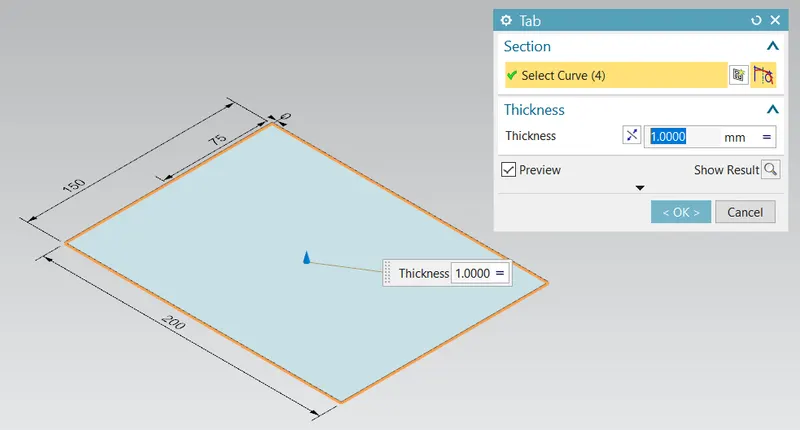
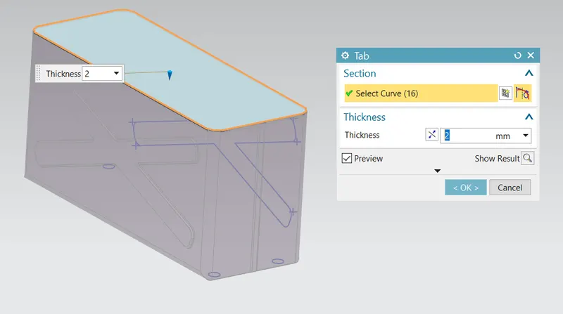
- Tab (for base of the box): Creates a base feature by extruding a sketch along a vector by a thickness value, or adds material to a planar face.
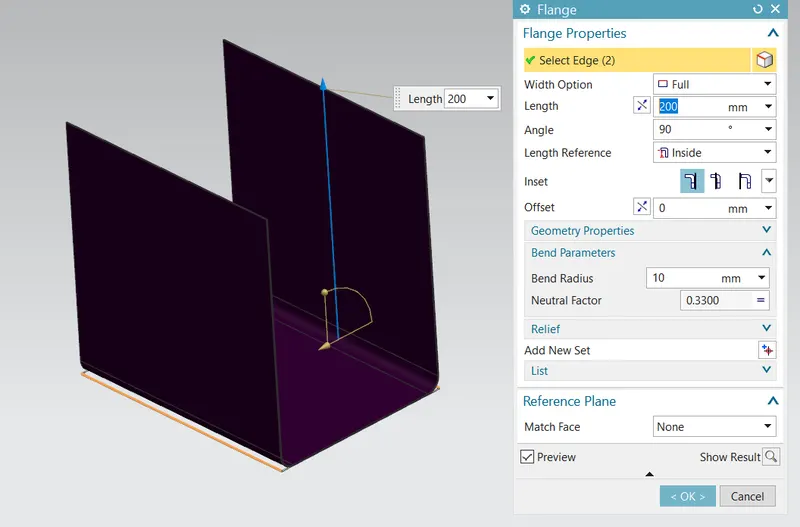
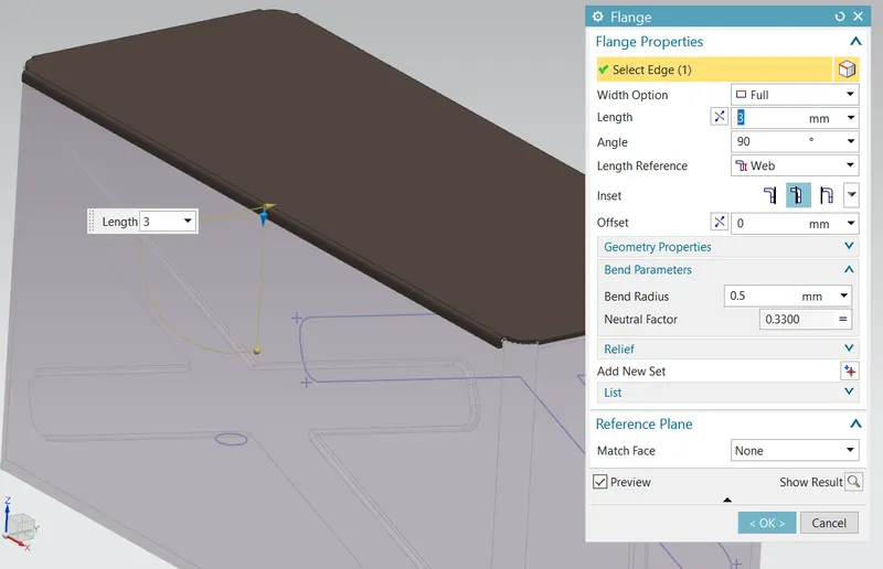
- Flange (for side walls): Adds a flat flange at an angel to a planar face and adds a bend between the two.
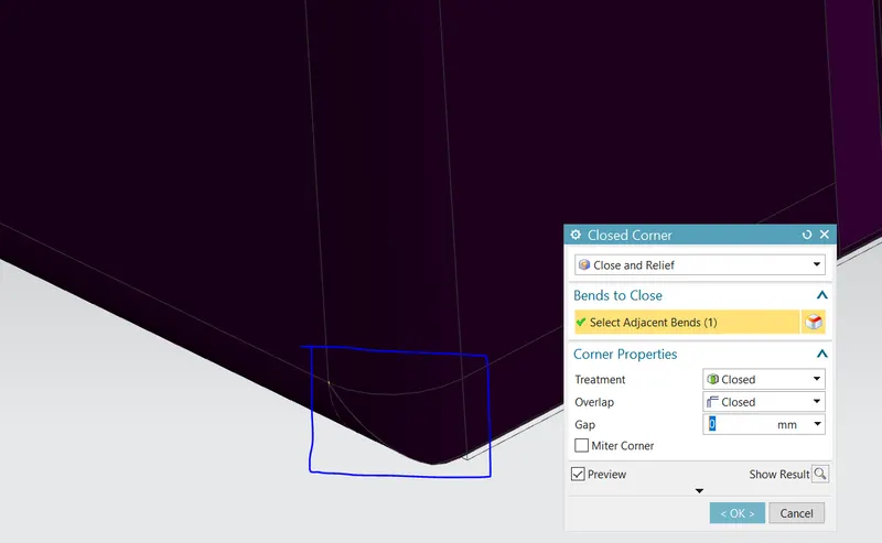
- Closed Corner: Closes a corner where two adjacent flanges meet by extending the beads and flanges.
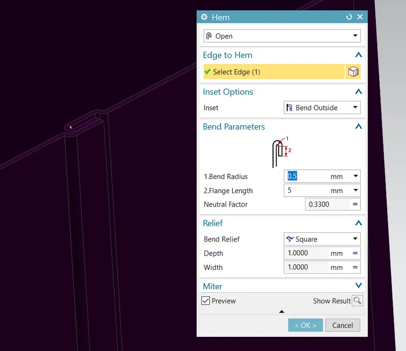
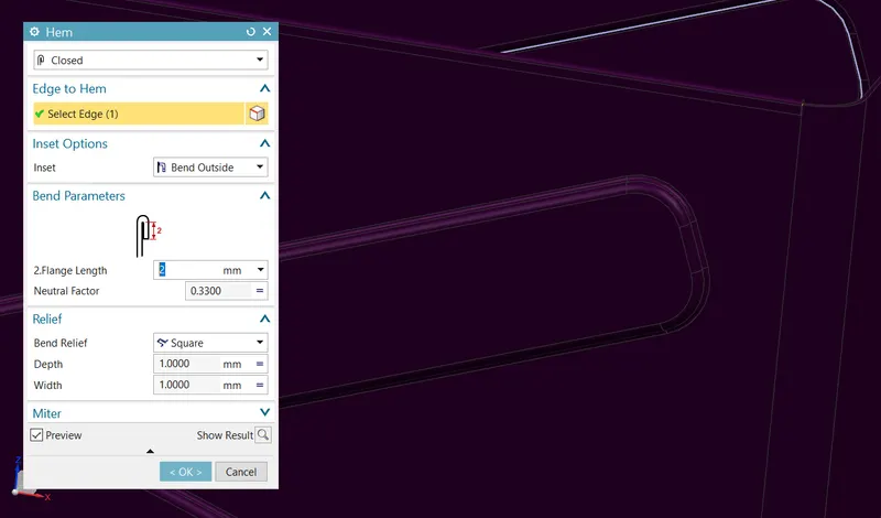
- Hem Flange (for closing the side walls): Modifies the model by folding the edge of a sheet metal flange over onto itself for the purpose of safe handling or to increase edge stiffness.
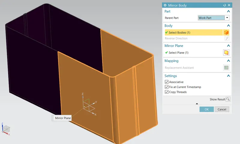
- Mirror Body: Copies a body and mirrors it across a plane.
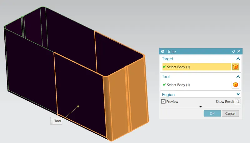
- Unite: Combine the volume of two or more solid bodies into a single body.
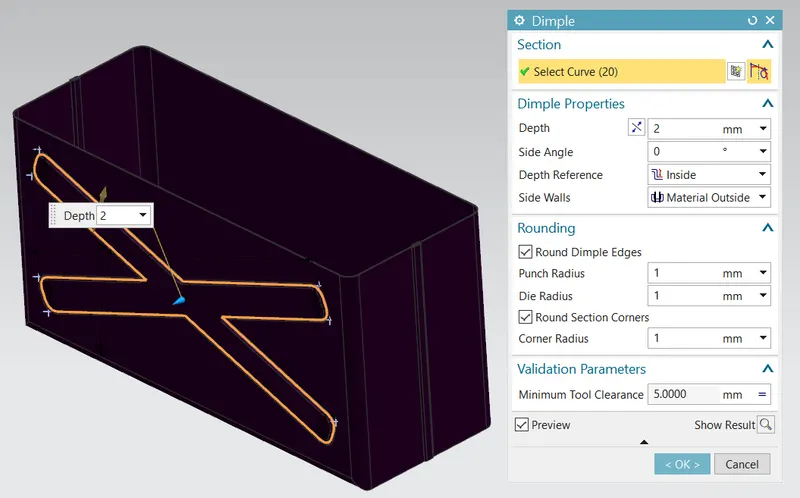
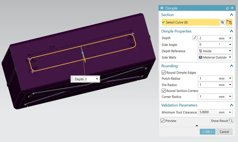
- Dimple: Lifts an area of the model inside a sketch that simulates a stamping tool.
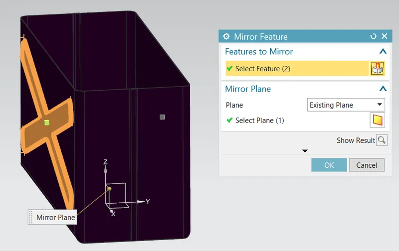
- Mirror Feature: Copies a feature and mirrors it across a plane.
- Dimple for the base
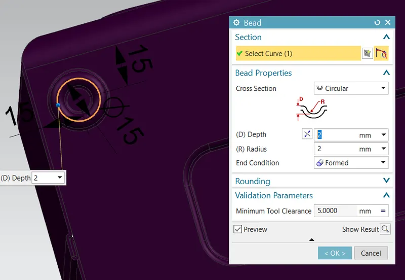
- Bead (also mirroring the bead on four corners): Lifts material along the contour of a sketch that simulates a stamping tool.
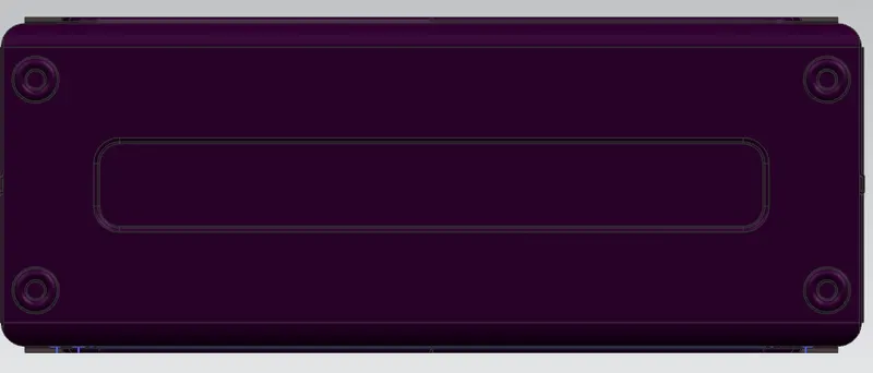
after mirroring the bead on the four corners
- Hem flanges (for the upper sharp corners of the box)
The Box is complete
2. Lid
- Tab for the Lid
- Flange for the 2 sides of the lid
The Lid is complete
3. Hinges
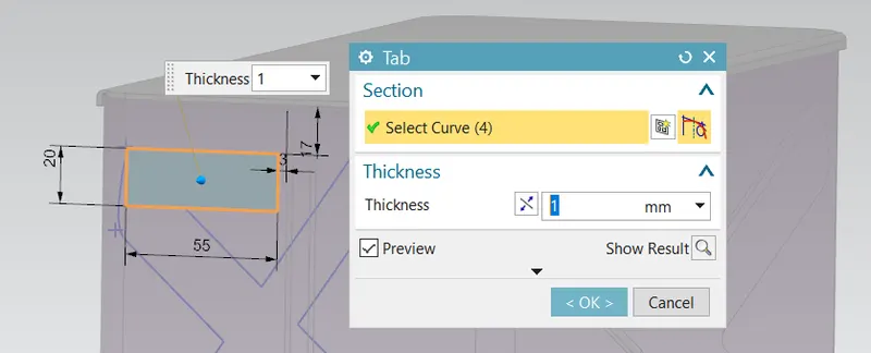
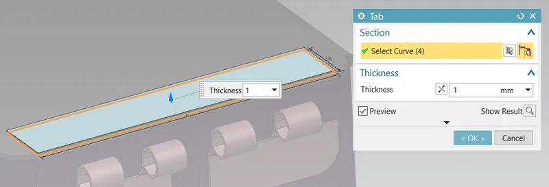
- Tab for the base of the flange on the wall of the box
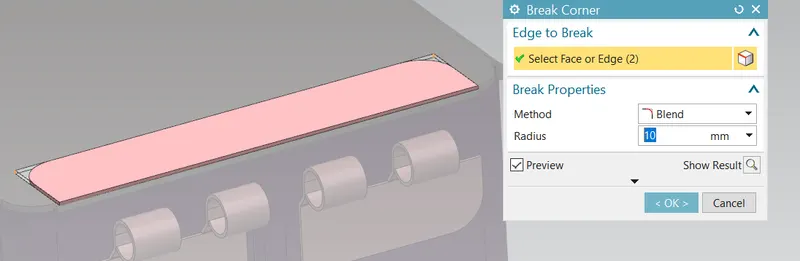
- Break Corner: Rounds or chamfers sharp corners of a tab or a flange.
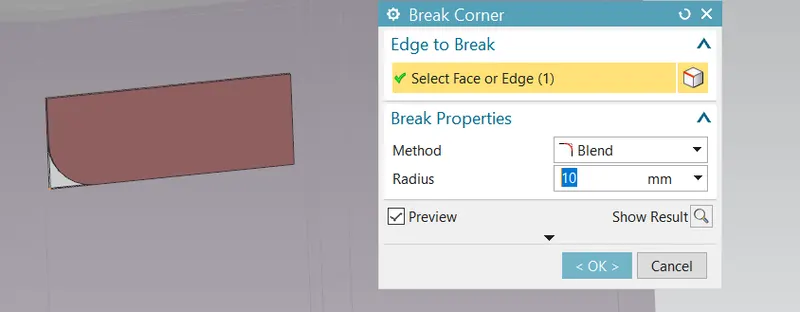
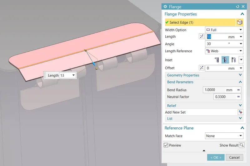
- Flanges for the Hinge body
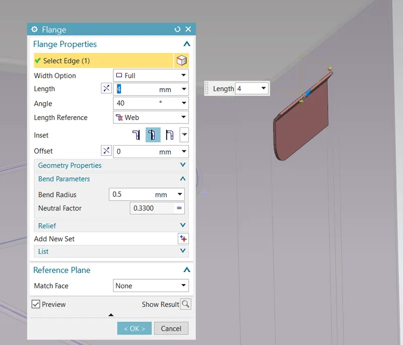
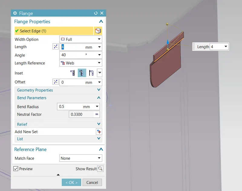
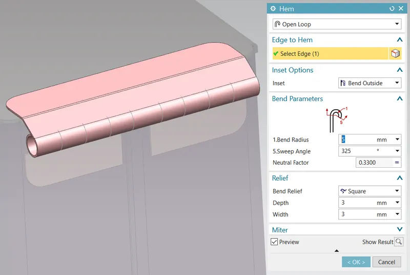
- Hem flange for the circular shape fo the hinge
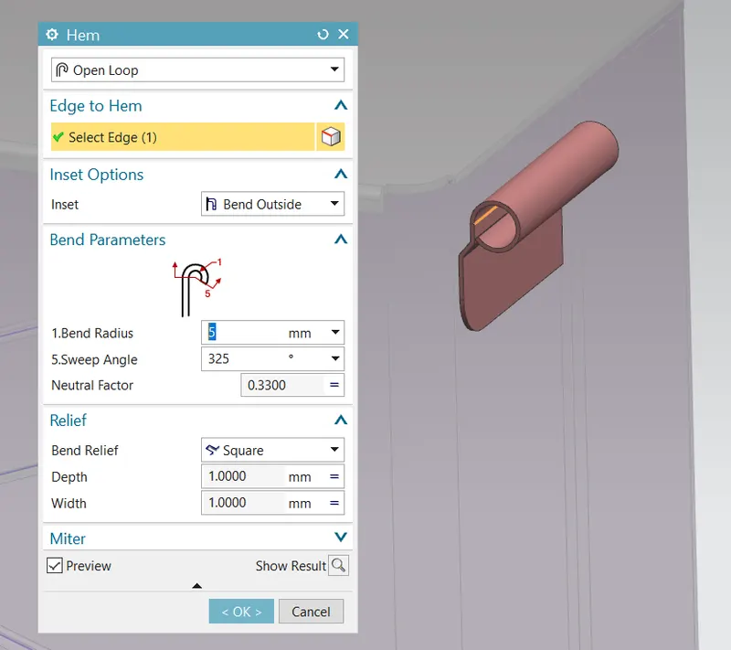
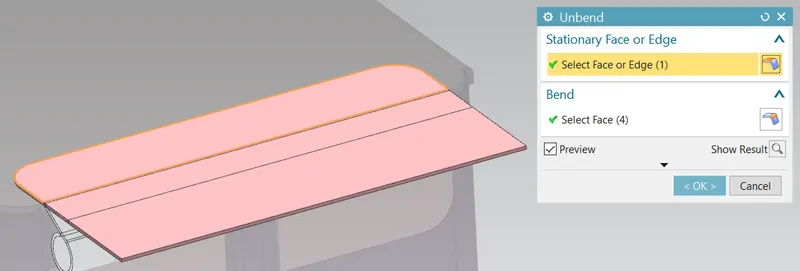
- Unbend for cutouts: Flattens a bend and the material adjacent to the bend.
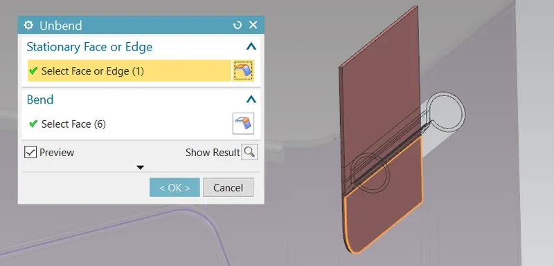
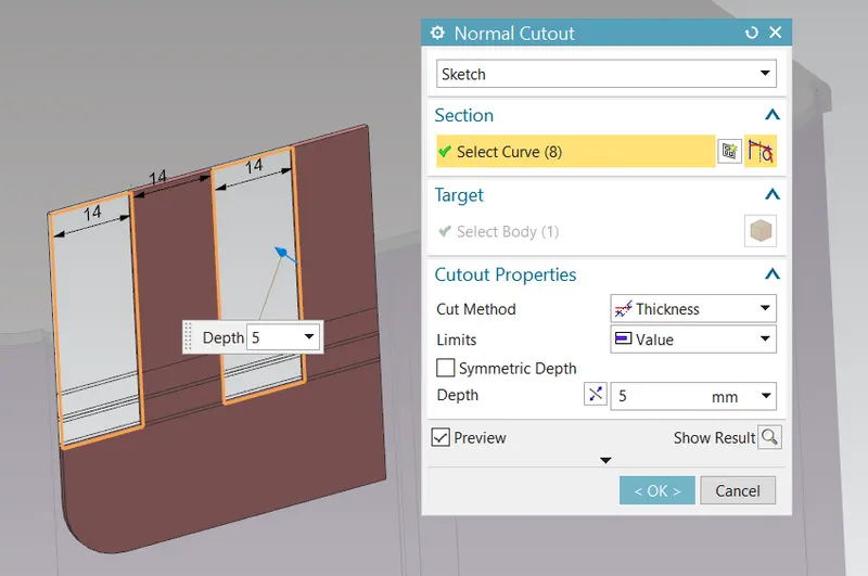
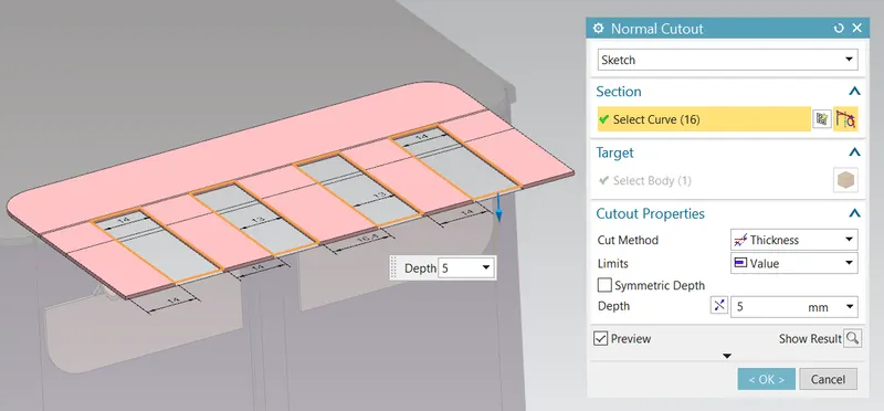
- Normal Cut: Cuts material by projecting the sketch onto the model and then cutting perpendicular to the faces intersected by the projection.
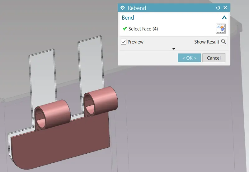
- Rebend after cutout: Restores an unbend feature to its previous bent state, along with any features added after the unbend feature.
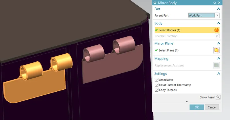
- Mirror Body to mirror the hinge onto the other side
- Tab for the Hinge on the Lid
- Break Corner
- Flange for the Hing body
- Hem flange for the circular shape of the Hinge
- Unbend for cutouts
- Normal Cutouts for aligning with the lower hinges
- Rebend after cutout
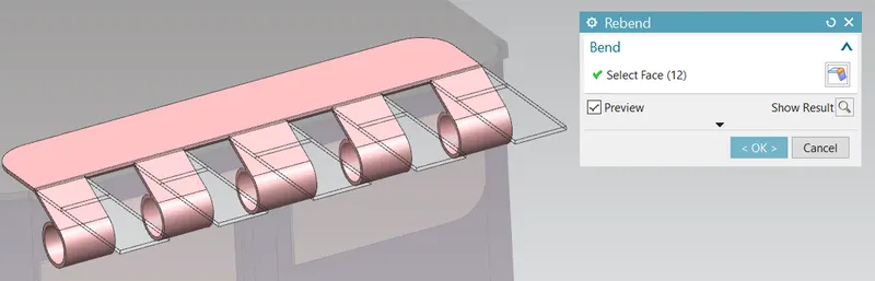
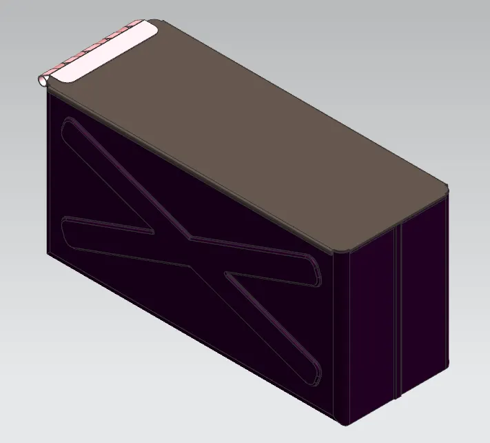
The Hinge is complete, thus completing the box assembly
Views of the Model
Front View
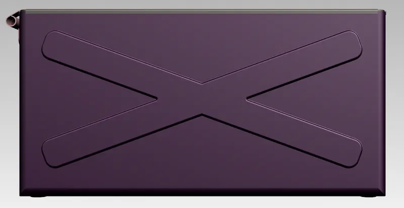
Bottom View
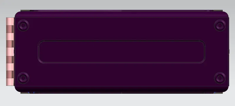
Side View
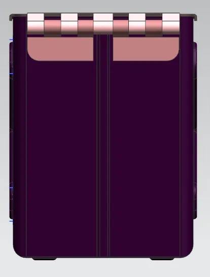
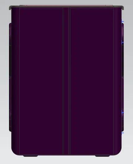
Top View
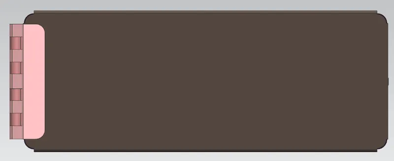
Isometric View
Conclusion
Thus, the Box Assembly was designed using the sheet metal workbench in NX-CAD by applying the sheet metal paramaters provided as input