Week 8 - Challenge 1 - Draft Analysis on a Fan Cover
FAN COVER - DRAFT ANALYSIS
Introduction
Draft Angle
Sheet metal and plastic parts that are made by forming, casting, pressing or even molding, require a draft angle at their side walls. Draft angles are the degree of taper that is incorporated into the side wall and cores of the die cast tool to aid in the removal of a part. Primarily, they function to reduce the friction between the part and the tool as it is ejected. Without draft angles, parts can be stripped, dented, or get stuck in the tool.
Draft angles are measured from the Tooling axis of the part. For mould designs where one metal mould component make direct contact with another, a minimum of 3° draft is required to ensure that the mould can separate properly.
Draft Analysis
Draft analysis measures the draft angle on multiple surfaces of a part along the tooling axis to check if the surfaces have the minimum required draft angle for it to be moulded properly.
Tooling Axis
Tooling axis is the direction in which the 2 halves of a mould (core and cavity) opens or closes, or the direction in which the part is released from the mould.
Process
Creating a Tooling axis
- A tooling axis should be created such that, the surfaces of the part must clear the tooling axis and the elements of the component can be created in that direction.
- For creating the tooling axis, we first intersect the component with the perpendicular planes, i.e, XZ plane and YZ plane.
- From the intersected surfaces we draw two lines from the boundary of the surfaces that we find close to not fulfilling the tooling axis.
- We then bisect these lines and get the tooling axis for the respective direction, i.e. X or Y direction.
- We then bisect the tooling direction created in the X and Y direction and get our final tooling axis.
Interstion with the XZ plane
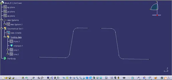
Creating two lines and bisecting them to get the X axis tooling direction
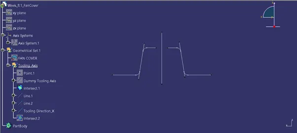
Intersection with YZ plane
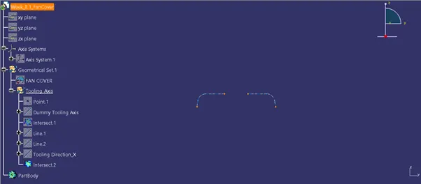
Creating two lines and bisecting them to get the Y axis tooling direction
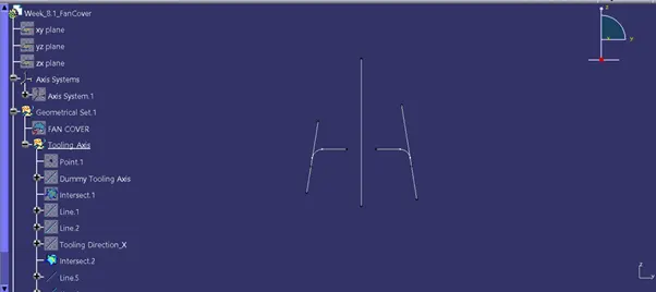
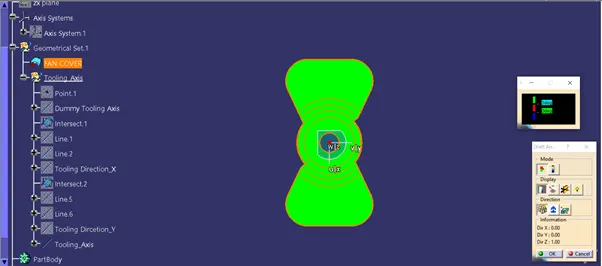
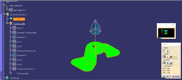
Final tooling axis by bisecting the axis of X and Y axis
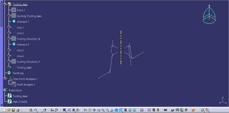
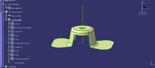
Draft analysis of fan cover along tooling axis
Front view
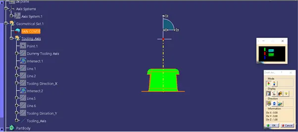
Side View
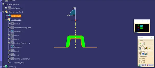
Top View
Isometric view
Conclusion
Thus, we successfully created the tooling axis for the Fan Cover and did the draft analysis for it along the tooling direction.