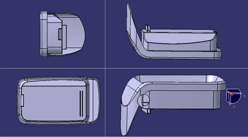
Week 9 - Attachment Feature Creation - Challenge 1
Design of Rib for Coin Holder
Introduction
Ribs
Ribs are thin wall-like structures that add support and rigidity to injection moulded parts. They are thinner than primary walls and are used to support these walls, as well as bosses, by running perpendicular to these structures. Ribs are often used to replace thick wall sections to avoid sink marks, warp, and voids.
Design rules for Rib creation
- Draft – minimum of 0.5° per side
- Thickness – generally 40% of wall thickness
- Height - ≤ 5 x wall thickness
- Spacing between ribs – rib height / width ratio, preferred 2:1, and a maximum of 3:1
- Thickness of Tip – minimum of 0.75mm
- Radii – maximum of 0.25
Process
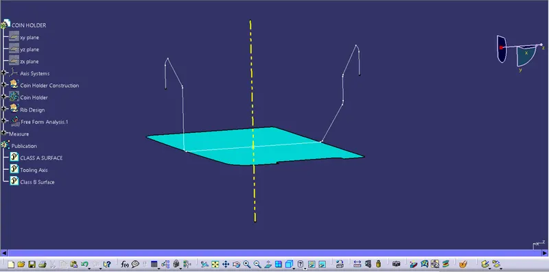
Creating Tooling axis
The tooling axis for the coin holder is made perpendicular to the base surface along the Y axis since the faces of the coin holder are not at a draft angle
Rib design
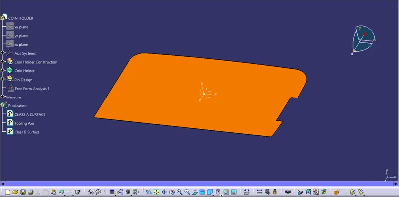
- We extract the bottom surface of the coin holder where the ribs are going to be made
- Creating a midpoint on the surface we get an axis system on it
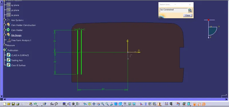
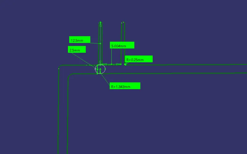
- A sketch for the ribs is made on the ZX plane, with the two ribs being at a distance of 6mm including the 1st rib thickness, which is at a ratio of 3:1
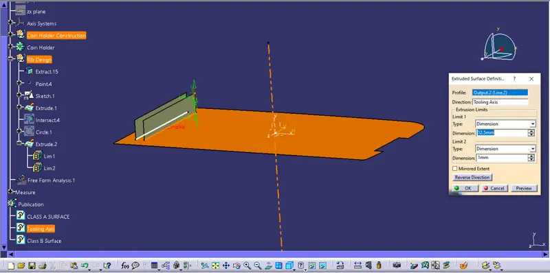
- The sketch lines are extruded along the tooling axis by a height of 5 times the thickness of the part, i.e. 12.5mm
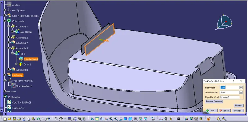
- The extrude is then thickened by a value of 0.4 times of wall thickness i.e. 1mm
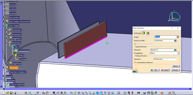
- A 0.5° draft is provided to the ribs on all 4 sides
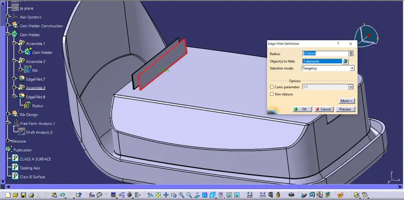
- All the faces of the Rib are then provided with a fillet of radius 0.25mm
Bottom face extraction and point and axis creation
Sketch for the ribs
Surface extrusion along tooling axis
Thickening of extruded surface
Draft for the ribs
Fillet for all the edges of the ribs
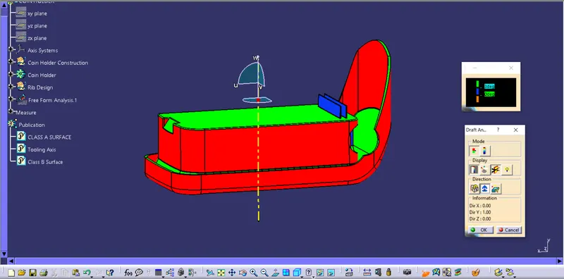
Draft Analysis
Report
- Faces in green have a draft angle of 3 degrees
- Those in blue have a draft angle lessern than 3 and greater than 0 degrees
- The faces in red either have negative draft angle or angles greater than 3degrees
Views of the model