Core & Cavity Design using Catia V5
Aim: To design core and cavity for switch bezel design.
Design procedure:
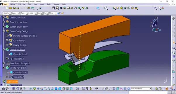
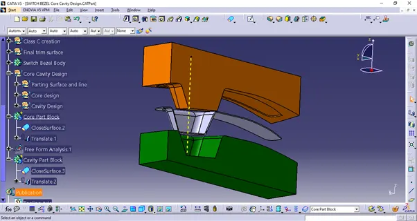
In core and cavity design, there are 4 major elements considered; Core, Cavity, Parting Surface and parting line. Core and cavity are the two halves of complete mould in which either of them is fixed and other one is movable. During injection moulding, core and cavity is pressed against each other tightly to create hollow space and avoid leaking of material. The surface where the two halves are joined is called parting surface. The outline of the component at the parting surface is called parting line.
In the draft analysis, component is observed for parting line. The surfaces having positive draft will be cleared in core side. In switch bezel, parting line is observed at B surface side.
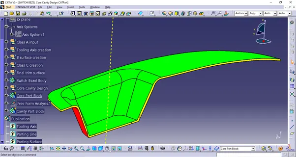
To get the parting line, Trim having class A and C surface is intersected with class B surface. The intersection boundary is called the parting line. Then the B surface is split with the parting line. The resulting surface is parting surface.
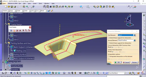
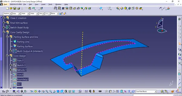
For Core design, class A surface trimmed with class C surface is taken. The required trim is taken from component design constructions.
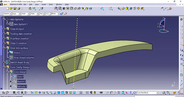
Then it is trimmed with B surface considering outside of B surface as parting area.
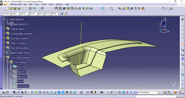
A sketch of rectangle is drawn in top view and it is extruded along the tooling direction.

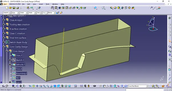
These two surfaces are then trimmed to get core shape. Top of the extrude is closed using fill surface operation to get the closed volume.
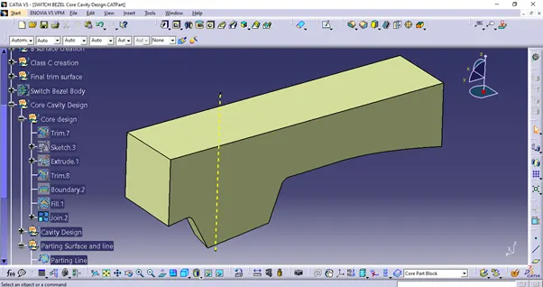
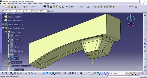
This closed volume is then converted into solid body.
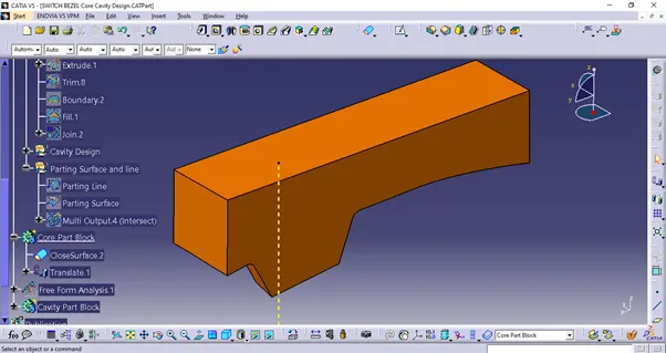
For Cavity design, B surface is trimmed with the rectangular extrude. The bottom open part is closed to get closed volume. This closed volume is then converted in solid body.
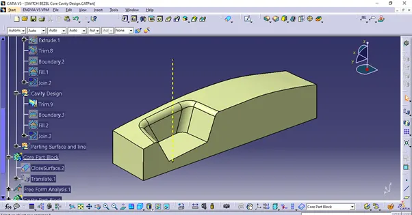
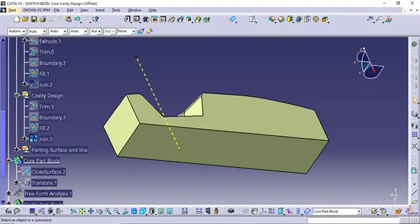
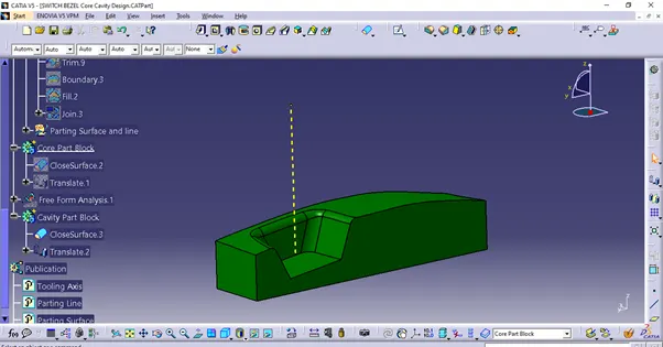
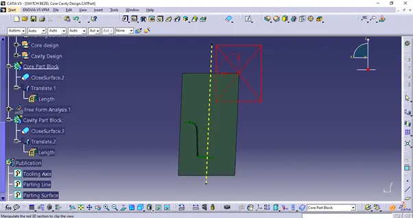
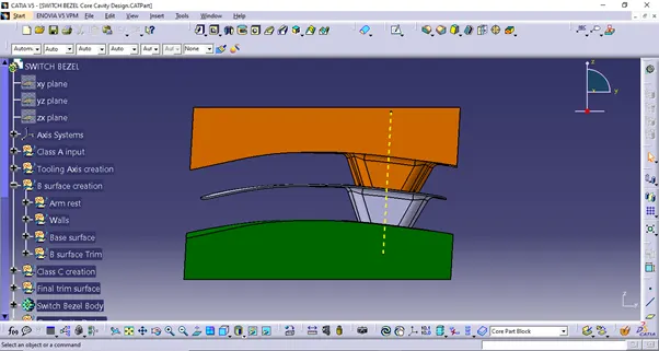
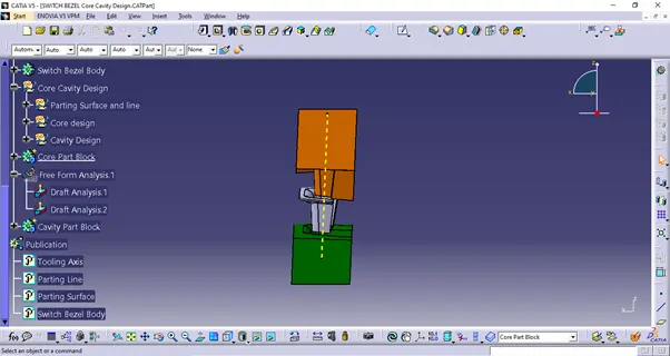
Section of complete mould
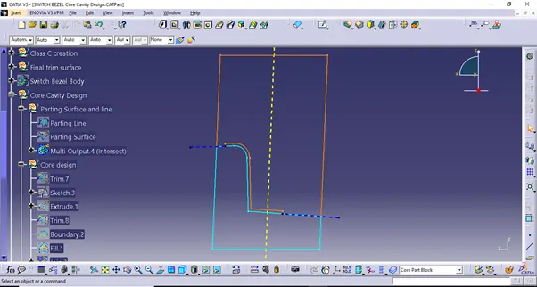
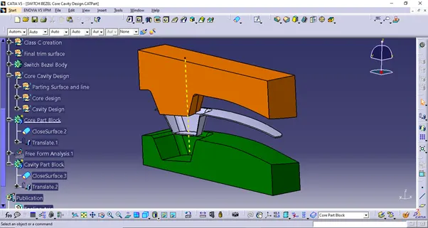
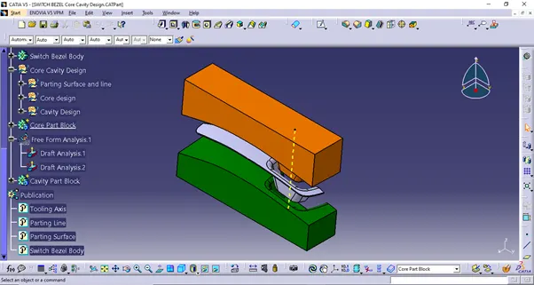
Mould Open position