B pillar design using Master Section
Aim: To design plastic B pillar along with B side features using provided class A surface and master sections.
Objectives:
- To create tooling axis for the component.
- To design class B and C surface from given class A.
- Add B side features like Dog house, 4-way locator and Ribs to component.
- Perform draft analysis on the component.
Introduction:
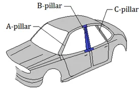
The B pillar is the vertical support in the car located between front door and rear door. It is a sheet metal part attached to the BIW of the car. B pillar trim is the plastic component, which acts as a cover for the B pillar to make it look aesthetically good. B pillar trim is manufactured using injection moulding techniques and attached to the BIW with plastic attachment features.
Design Procedure:
- Creating tooling axis
At first tooling axis is created for the component to determine core and cavity opening directions. It is created using the provided master section.
In the given two master sections, it is observed that at the intersection of master sections, there is a 4-way locator on the dog house. The sides of this 4-way locator will be used to create tooling axis.
To get a point from which tooling axis will pass, bottom line of 4-way locator is extracted and a point is created at the middle of the extract.
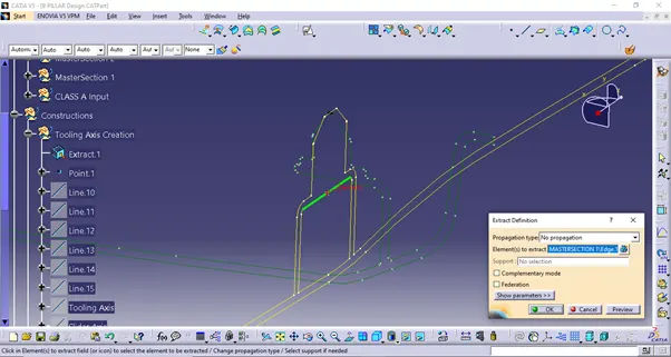
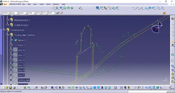
Then all 4 sides of the locator are extracted from the master section.
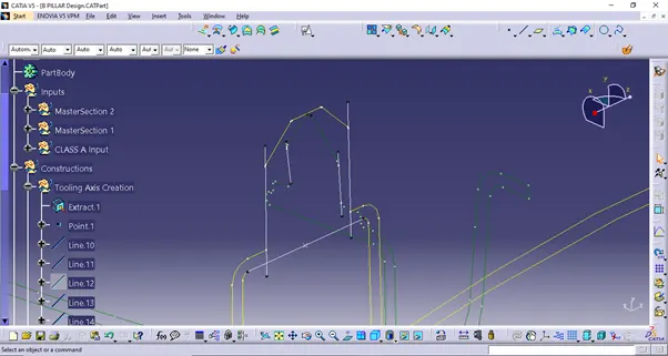
A bisecting line is created from the opposite sides of the locator passing through the point on baseline extract.
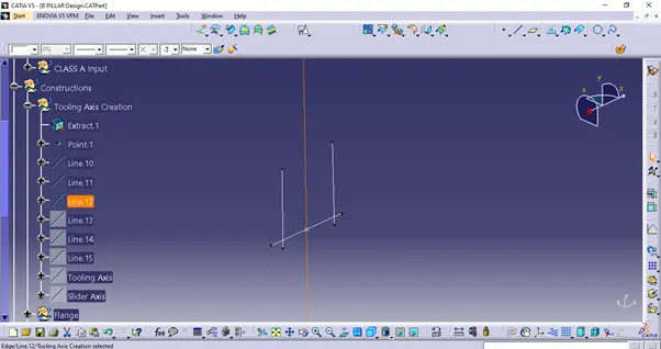
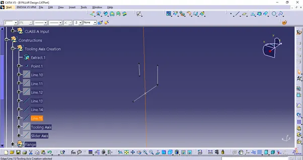
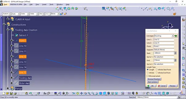
Then a bisecting line using these two resulting lines is created. This will be the final tooling axis for the component.
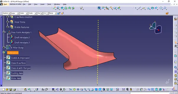
To check the validity of tooling axis draft analysis is performed on class A surface. Draft analysis is selected from insert menu and then using the compass, the draft direction is selected as tooling axis by coinciding compass with tooling axis and the class A surface is selected.
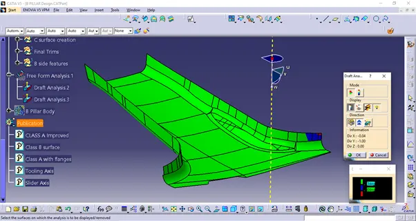
From the draft analysis results, it was observed that all the surfaces fulfil the condition of 3-degree positive draft except one patch as shown below.
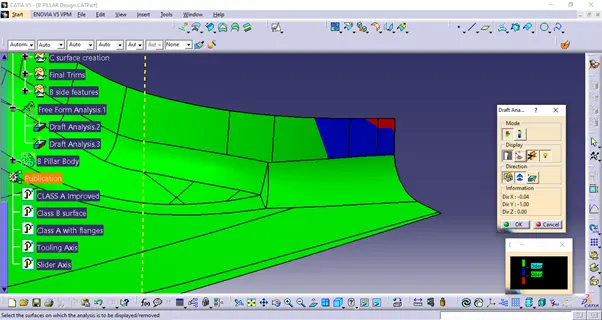
Since it is a very small patch with negative draft of minimal value of -0.2 degrees, design of the component is proceeded but this problem will be highlighted to the class A team.
- Flange creation using master section
To create flanges on the edge of the class A surface, area near the edge is extracted and its boundary is extracted.
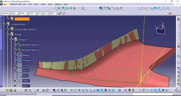
This extracted edge is then swept using sweep command. In sweep command, with reference surface option is used and extracted surface is given as support.
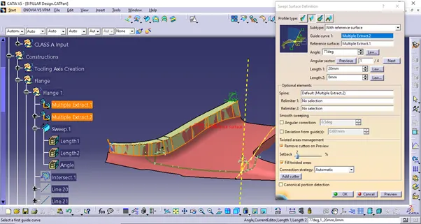
The intersection of swept surface and plane at master section is taken to observe if the flange is proper or not. After some changes in the sweep angle, the sweep surface is offset to match with the master section.
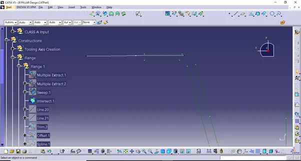
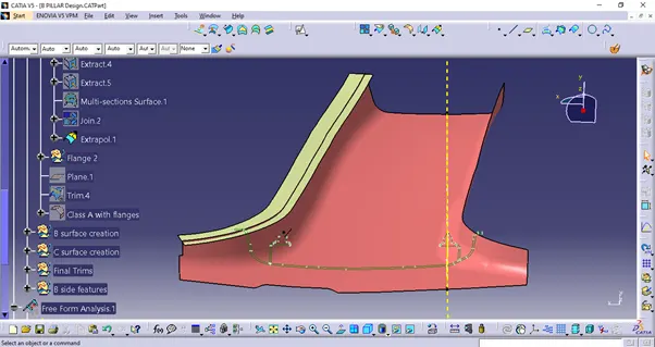
Similarly flange at the other edge is created and the both the flanges are trimmed with the class A surface to get final output of class A surface with flanges. Fillet is applied at the sharp intersection of class A and flanges.
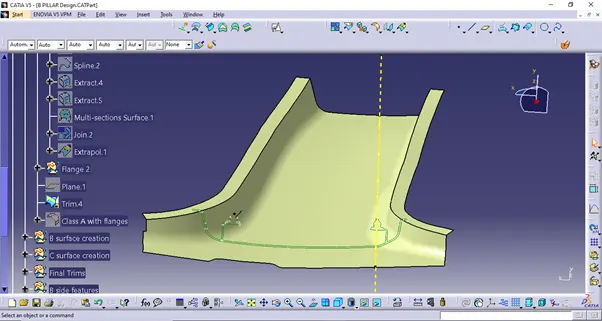
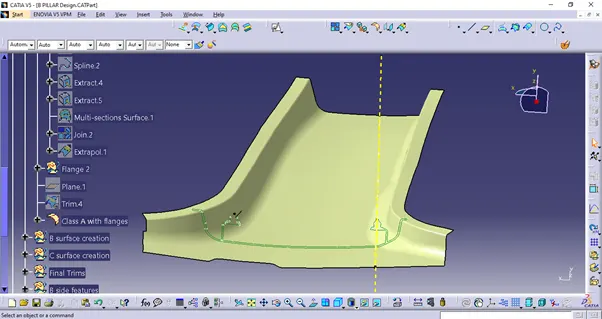
- B surface creation
Since the given class A is a complete styling surface and does not have any defined fillet values or intersections, to get the B surface, simply the complete A surface with flanges is made offset at the distance of 2mm.
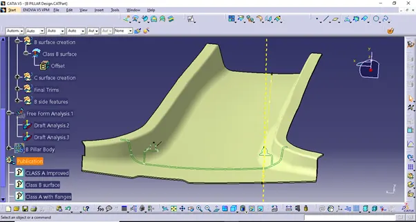
- C surface creation
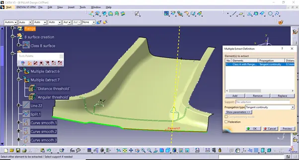
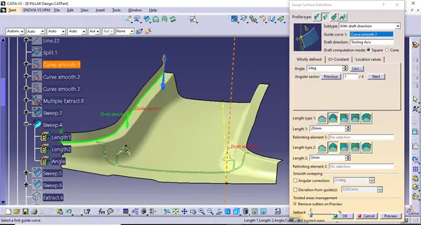
To create class C surface, all the edges of class A with flanges are extracted and converted to smooth curve. Then Sweep with draft direction option is used to create C surface at 3-degree angle with respect to tooling axis.
Some areas of fillet are treated manually by creating multi section surface in between.
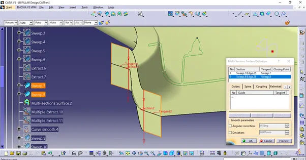
Then all the C surfaces are trimmed together to get the final class C surface. If the swept surfaces are not intersecting, they are extrapolated to get the intersection.
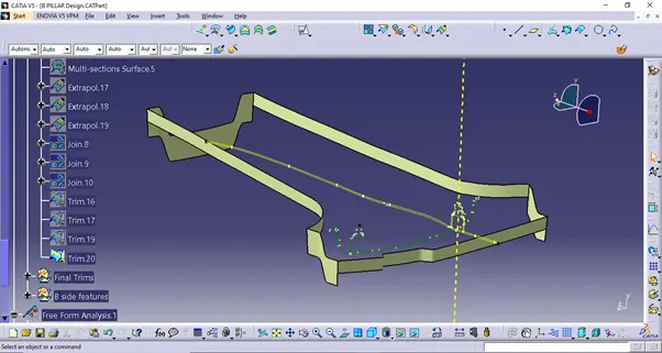
- Creating final closed volume and converting in solid body
All the three surfaces, Class A, B and C are then trimmed and joined in such a way that they form a closed volume without open boundary. Then it is converted into solid body using closed volume option in part design workbench.
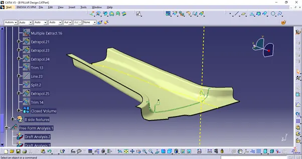
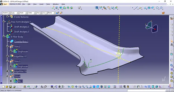
- B side feature creation: Dog house with 4-way locator
Dog house is an engineering feature used on B side to increase the length of screw boss or locators. This allows to have a long attachment feature with better strength and no sink marks.
To create dog house from master section, a positioned sketch is created using plane and point at the place of dog house. In this sketch, the inner profile of the dog house is projected from master section. This profile is extruded in both directions for certain value.
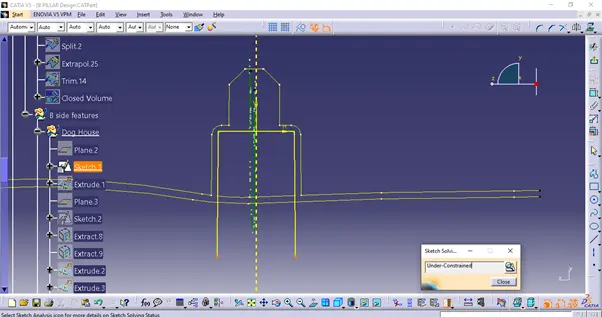
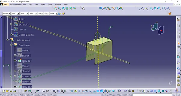
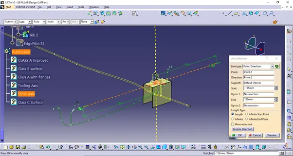
A line is created in the direction of extrusion. This line will be considered as Slider axis.
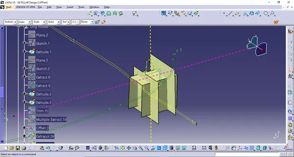
Then two lines are extracted from master section and extruded to specify start and end limit of dog house.
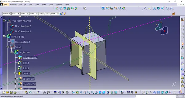
Dog house profile is trimmed with end limit and then thickened to 2mm. Then the resulting body is slitted with start limit to get open end of dog house.
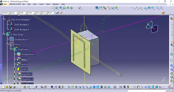
To avoid sink marks on class A, the bottom of dog house is made 40% of the part thickness as per design guidelines. For that offset of dog house inner walls and bottom class A surface is used.
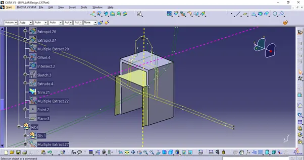
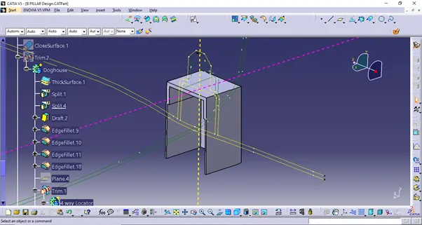
The inner faces are drafted along the slider axis for easy removal of slider. Then fillet is applied on all sharp edges.
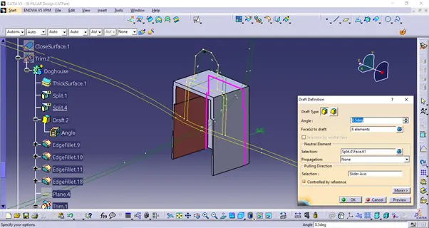
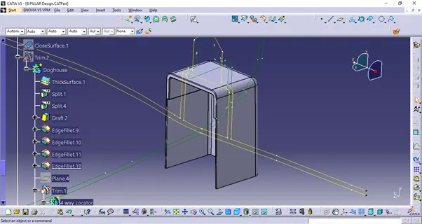
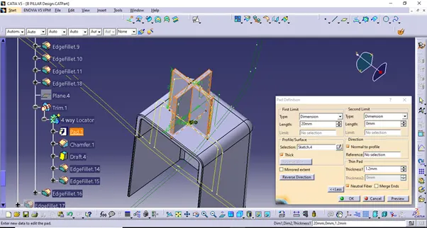
A 4-way locator is created on the top of dog house. To create this, a positioned sketch is created on top and extruded by giving thickness value of 1.2mm.
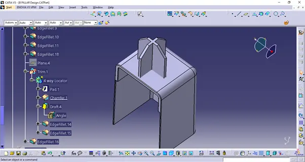
Chamfer is applied at the edges and then all faces are drafted along the tooling direction. Fillet is applied at all sharp edges.
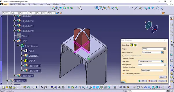
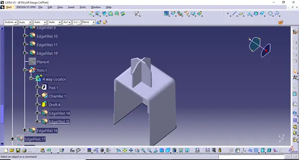
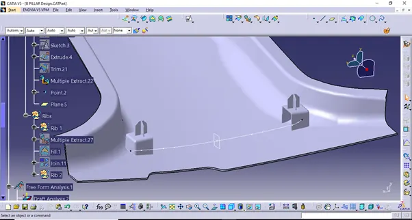
The same dog house with locator is copied and pasted with link. Then it was made symmetric on the other side of master section using plane at middle of it.
Then both dog houses are added in main body using union trim.
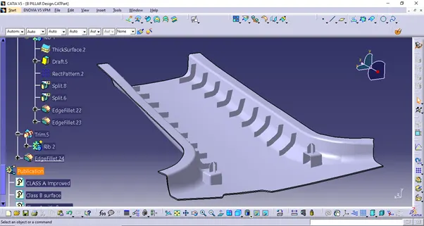
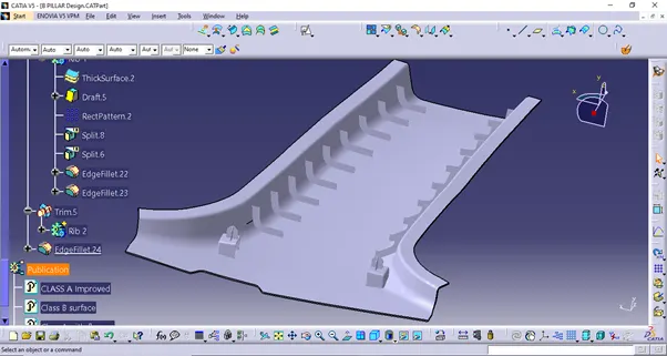
- B side feature creation: Rib creation
Ribs are the supporting members which prevents the bending of surfaces and provides strength to the component.
To start creating ribs, a positioned sketch of line is created. This line is extruded and thickened to the value of 0.8mm. This rib is also provided with draft along tooling direction. To create multiple ribs, rectangular pattern option is used. It is patterned along the line created through the edge of B pillar at an interval of 55mm.
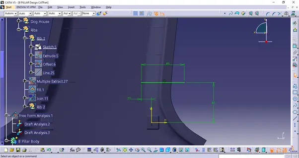
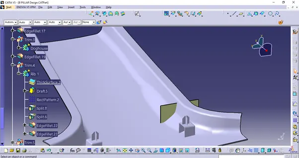
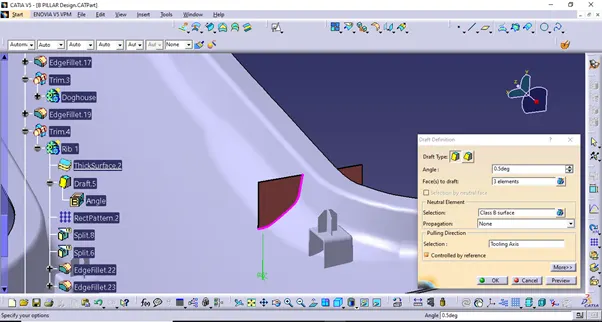
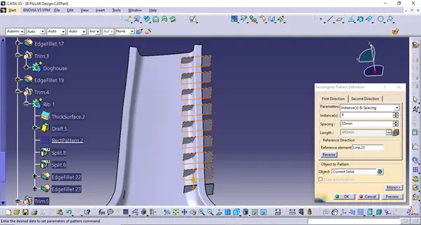
Since the rib height can be 5 times the thickness of component, B surface is made offset at distance of 10mm. These ribs are then split with this offset surface. Also, from other end it is split with class A surface.
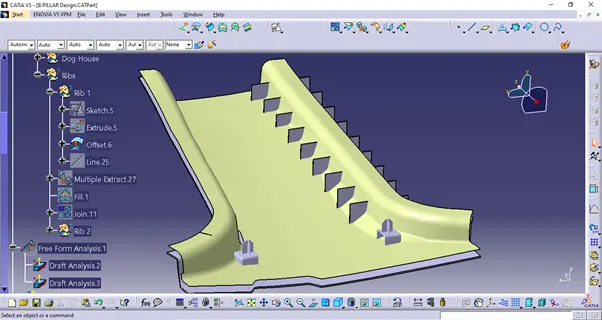
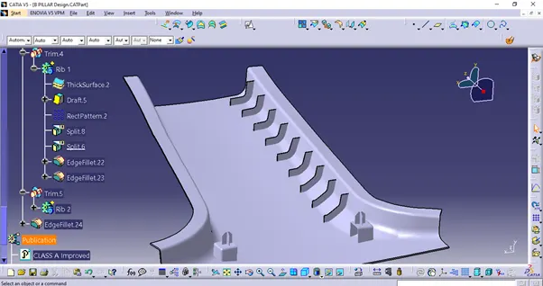
Similarly, Ribs are created on other side. All sharp edges are treated with fillet and Ribs are combined in main body with union trim.
- Draft Analysis on the component
Draft analysis is performed on the final component to check its manufacturing ability. Draft analysis is performed using main tooling axis and slider axis.
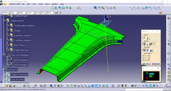
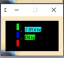
All the faces of class A have a minimum draft of 3 degree except the following mentioned faces.
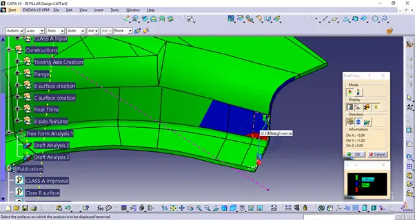
These faces in blue have positive draft but red faces have draft of -0.148 degrees. This will be communicated with the class A surface designer.
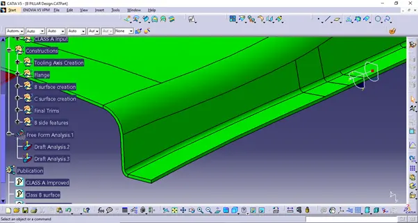
Class C surface is tooled along with class A surface and fulfil the criteria of minimum positive draft.
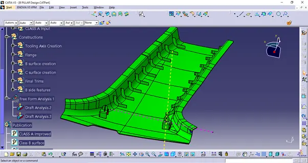
For B side surface, all surfaces including attachment features have minimum draft of 0.5 degrees except the following surfaces.
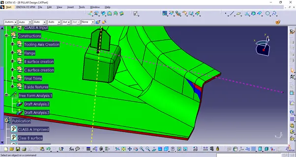
The surfaces in red have negative draft, but can be ignored as it is a very less area and negative draft in class A is informed to the class A team.
Draft analysis in slider axis direction:
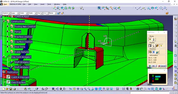
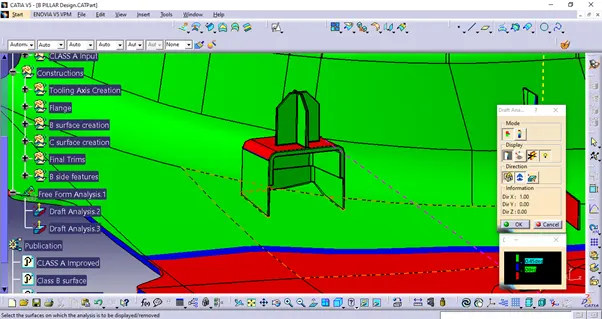
In slider axis direction, all the internal faces of dog house have minimum draft of 0.5 degrees.
Conclusion:
The design of B pillar trim is completed and from draft analysis it is observed that the design is safe to manufacture except some imperfections which will be communicated to the class A team.