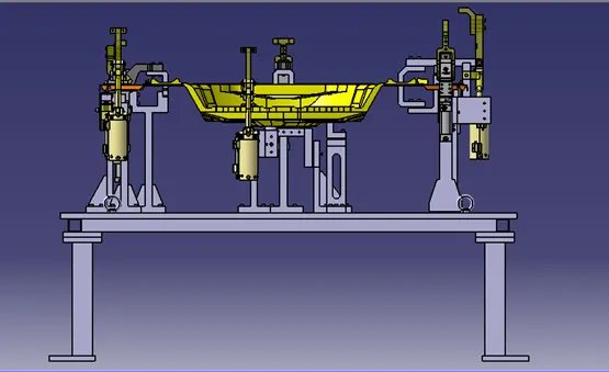
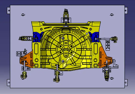
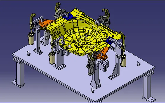
Base Unit Design for Fixture assembly
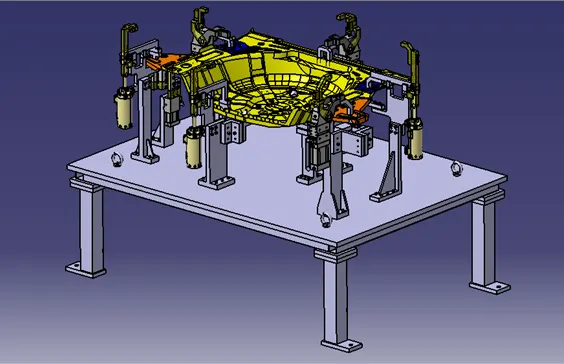
Aim: Design of Base unit with all weldments for given car panel, design of fixture assembly to constrain all 5 panels.
Introduction:
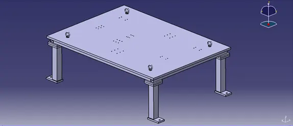
The base unit is designed to mount all the other units like clamp unit, pin unit, rest unit, etc of the tool, also other parts like pneumatic valve box, trunking cable path will also be mounted on the base unit.
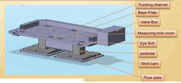
The various parts of the base unit are as follows:
- Base Plate
- Trunking channel
- Valve box
- Measuring hole cover
- Eye Bolts
- Pedestal
- Floor plate
Base Plate:
The base plate is a machined plate of 25 to 40mm thickness made of steel and aluminium, on to which the holes are drilled to mount the individual units like clamp unit, pin unit, etc. of a tool.
Trunking channel:
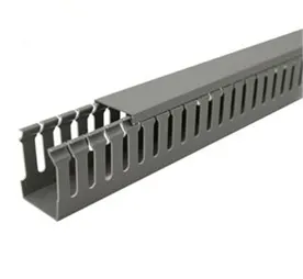
A trunking channel is a duct or hollow passage which accommodates and guides all the pneumatic and electrical hoses and wires for the units of the tool.
Valve Box:
The valve box is a standard part that will accommodate the pneumatic valves for the unit. It consists of solenoid valves that control the supply of air to the cylinders of different units.
Measuring hole cover:
The measuring hole cover covers the coordinates of datum holes or reference holes. These coordinates are used as a reference while installing other units. Also, these holes are used for CMM inspection purposes.
Eye Bolts:
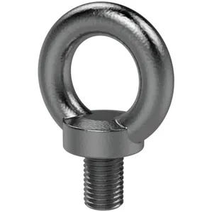
Eyebolts are used for the transporting of tool, using lift hooks. Forklift holes will also be provided in some cases for transporting purposes. When a complete base unit needs to be transported from one place to another, eye bolts are used.
Pedestal:
A pedestal is a part that connects the base plate to the floor plate. A pedestal is a standard part in general, and in some cases, it can be a welded frame integrated with the base plate.
Floor plate:
The floor plate is grouted to the floor with a fixed bolt on the ground. Floor plates are also called foundation plates.
The following points needs to be considered while designing the base unit:
- A base unit should cover all the units with its outer periphery including the opening.
- A base unit is preferred to be designed with respect to the body coordinate system.
- A base plate should be drilled with datum holes measuring holes in line with a pitch of 1000mm in general.
- The number of datum holes must depend upon the size of the base plate.
- The datum holes must be drilled at nominal values of coordinates and in terms of 50 and 100.
- Datum holes must be drilled with a diameter of 100mm away from other units.
- Datum holes must be covered with cover Plates.
- The height of the base unit depends upon the type of the welding fixture and the standard height of the worker of the specific country.
- The base unit may be built from simple sections so that other units may be fastened with screws or welded whenever necessary. Those parts of the fixture that remain permanently with the fixture may be welded. Those parts that need changes may be fastened.
Design Methodology:
The following components of the base unit are designed during this project.
Base plate:
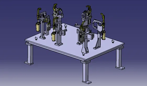
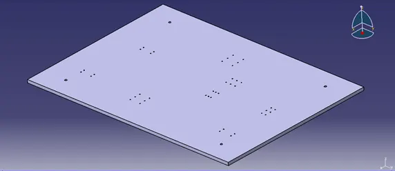
As per the fundamentals of base unit design, the base plate should cover all the units including the outer periphery. The base plate designed here is 1775mm X 1285mm. The thickness of the base plate should be 20 to 45mm. Here, it is taken 25mm. Holes for mounting pin and clamp units, eye bolts are created on a base plate.
Weld Frame:
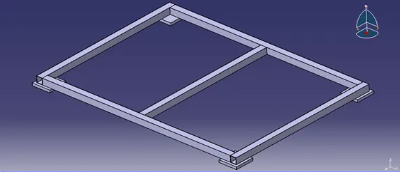
The base plate is welded to a weld frame made of square pipe. The frame of size 1715 X 1225mm is made with one middle support. The pipes used are of size 50 X 50 X 2mm. On the four corners, plates of size 150 x 150 x 20mm are welded.
Pedestal weld:
A pipe of size 80 x 80 x 5mm is used as a pedestal for a unit. The height of the pedestal is decided by the height of the floor from the panel. The distance here is kept at 900mm. This distance varies from organization to organization as per country standards depending on average worker height. The pipes of fitted with a plate of 150 x 150 x 20 on top which will be welded on the frame. At bottom plate of 180 x 100 x 20mm is welded which is provided with a threaded hole for leveling.

Base Unit:
Clamp Units:

Pin Unit and Rest Unit: