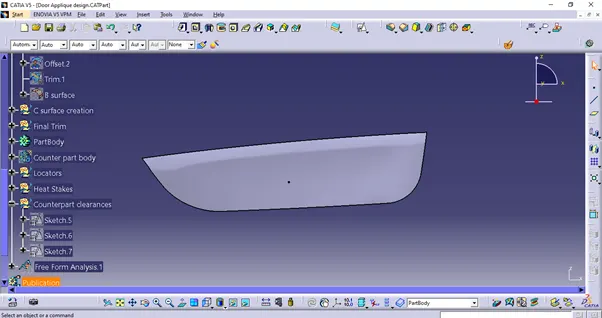
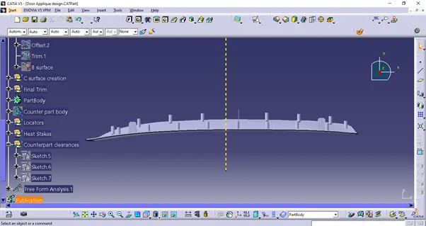
Door Applique Design with Engineering Features
Aim: To design door applique from class A surface with engineering features like locators and heat stakes.
Objective:
- To design door applique by creating B and C surface and converting in solid body.
- Create 4-way and 2-way locators.
- Create Heat stakes on B surface as attachment feature.
Procedure:
- Checking class A surface for irregularities.
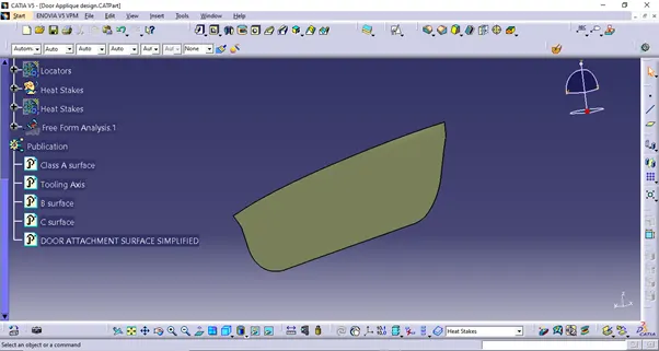
The given Class A surface is checked for any irregularities, fixed and joined as a single body.
- Tooling axis creation
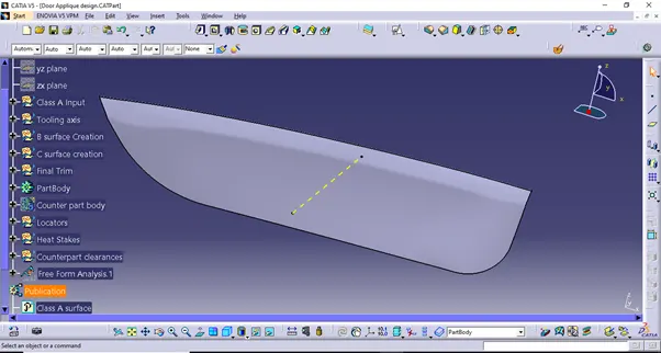
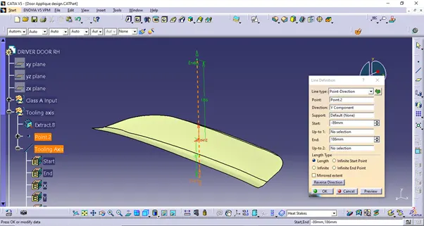
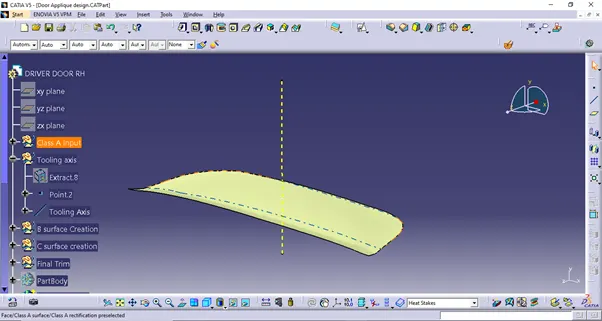
To get the tooling axis, one major surface of class A is extracted. A point is created at the middle of the surface. A line is created through this point in the Y direction. This line will be considered as tooling axis.
- Draft analysis on Class A Surface
Draft analysis is performed on the class A with respect to tooling axis, to check if all the surfaces of the class A fulfil the requirement of minimum draft.
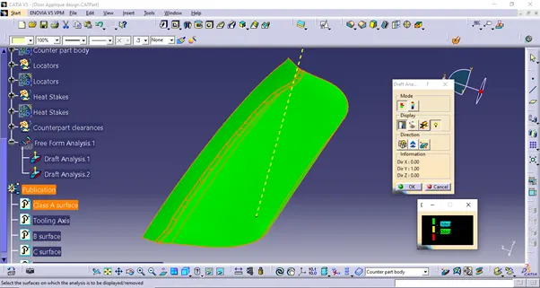
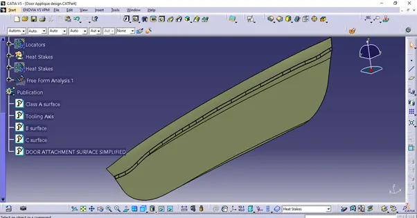
The surfaces in green shows that they are within the draft limit of 3 degrees. Hence, the tooling axis is valid for component design.
- B surface creation
Class B surface is created using extract, untrim extrapolate and offset commands. First all the surfaces except the fillet surfaces are extracted. These surfaces are untrimmed and offset to the distance of 2.5mm. Then extrapolated to intersect with each other. Then these intersecting surfaces are trimmed. Fillet is applied at the intersections as per material thickness.
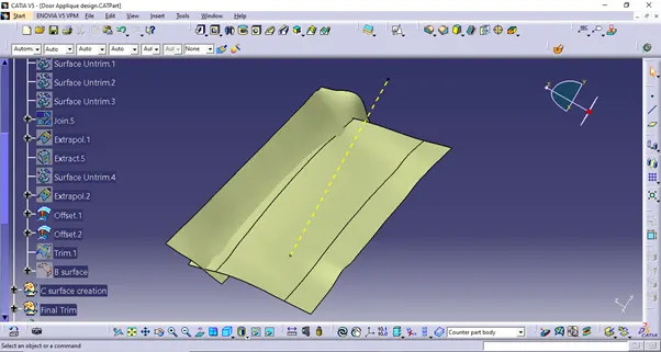
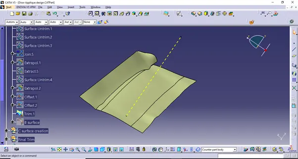
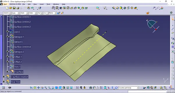
- C surface creation
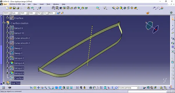
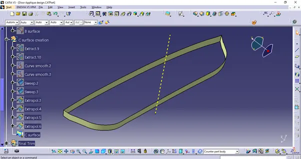
To create class C surface, Boundary of class A surface is extracted. It is extracted in two parts as per tangency continuity. These boundaries are swept using the tooling axis as draft direction. The resulting surfaces are extrapolated till intersection and then trimmed to get final class C surface.
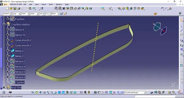
- Creating final closed volume and converting in solid body.
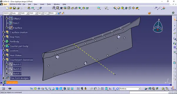
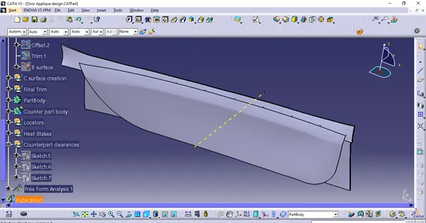
Finally, to get closed volume, class B and C surfaces are trimmed and then joined with class A surface. This closed volume is converted into solid body using part workbench command closed volume.
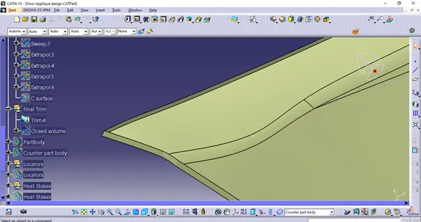
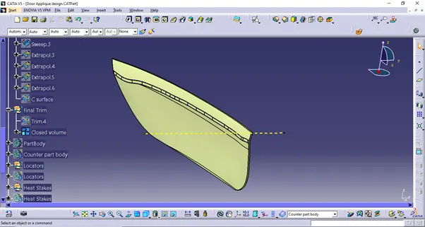
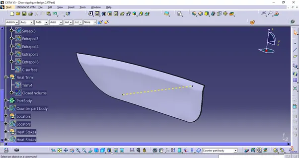
Draft analysis is performed on final solid body to check if all surfaces are within draft limit.
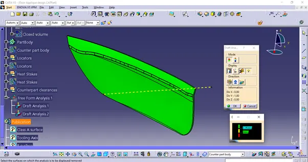
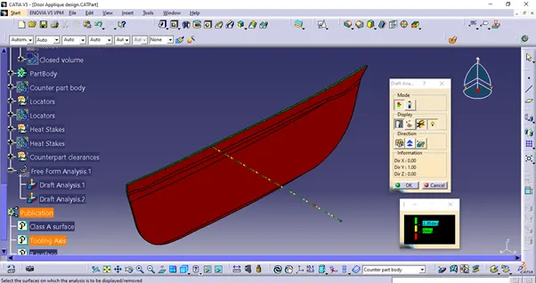
The draft analysis shows that Class A and C are green that is positive draft and B surface is red that is negative draft. This shows that design is valid with parting line at the intersection of B surface and C surface.
- Creating engineering features like locators and heat stakes.
While joining the plastic component with its counterpart, locators are used to locate its position and heat stakes are used to create permanent joint between two components without using any external fastener. Locators are of two types; 4-way locator and 2-way locator.
To create 4-way locator, the base surface is extracted and a point is created at the centre. A reference plane is created through this point parallel to X-Z plane.
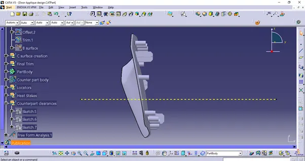
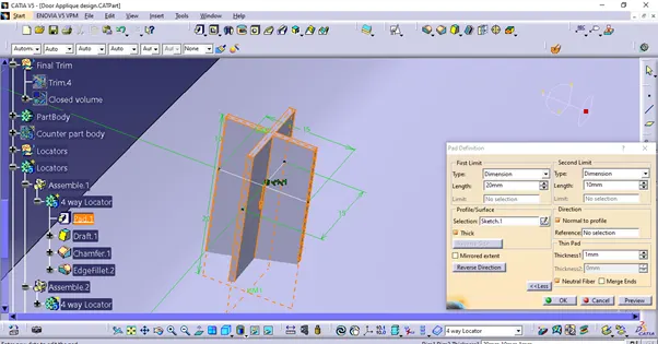
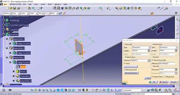
A sketch is created and created a pad with thickness value of 1mm. The length is kept such a way that it intersects with main body and overall length remains 20mm.
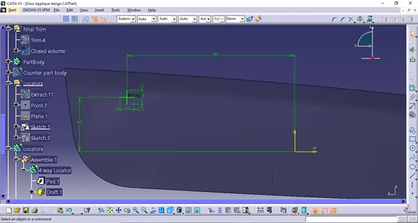
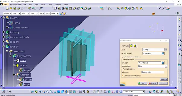
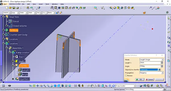
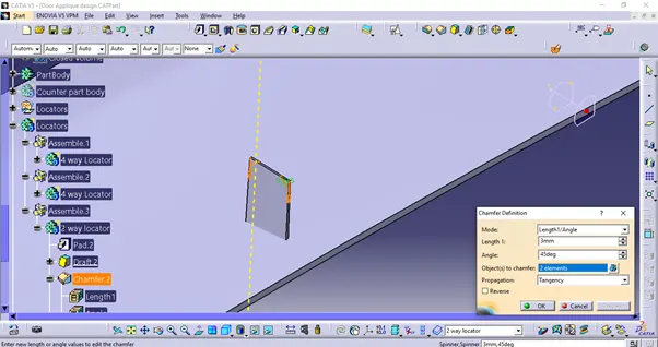
Draft is applied on all surfaces in the direction of tooling axis for smooth ejection. A chamfer of 3mm is provided and fillet of 0.25mm is applied at all sharp edges.
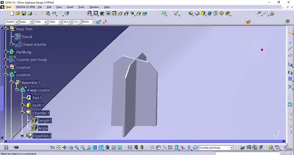
A second 4-way locator is created at other end by creating a copy and translating the same to different position.
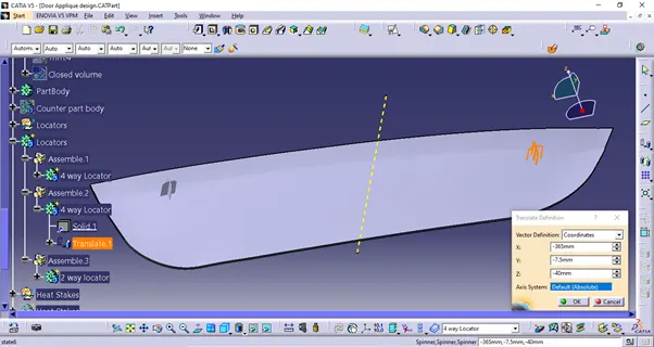
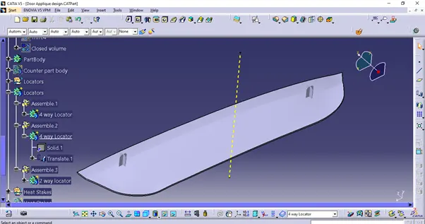
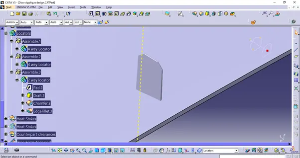
One 2-way locator is created at bottom side using the sketch of the line. This locator is also created by giving draft, chamfer and fillet as that of 4-way locator.
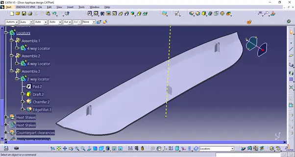
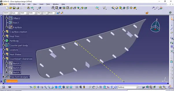
Heat stakes are located near the edges of component. For that, B side of the component is extracted and its edge curves are made offsite on surface. A number of equidistant points are created on curve as per required number of heat stakes.
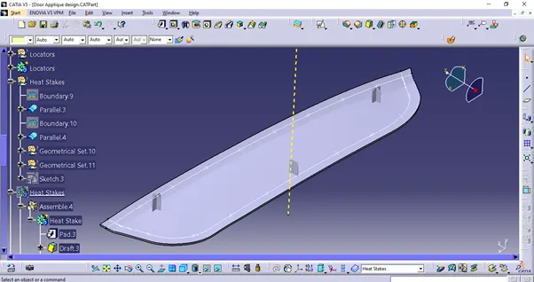
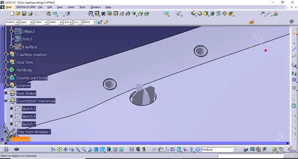
Heat stakes are created in the same way as locators. A sketch is used to extrude the heat stake body. The height of heat stake is kept lower than locator as locating will happen first then heat stakes come in contact with counterpart. Heat stake walls are also provided with draft.
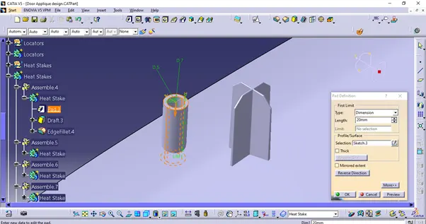
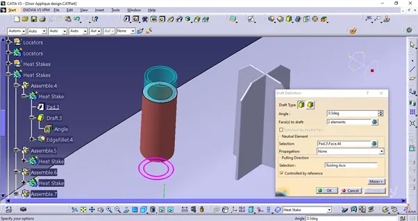
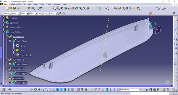
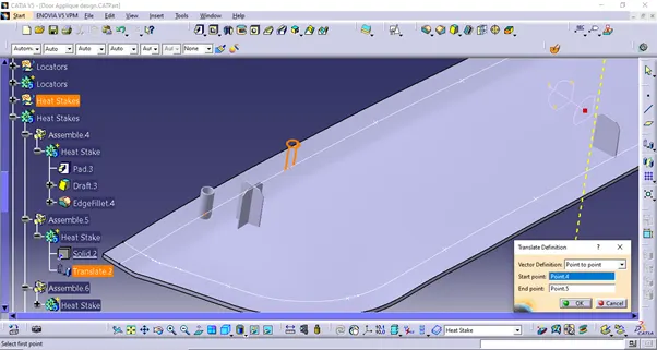
This body of heat stake is copied and translated at all points on the curves using translate option.
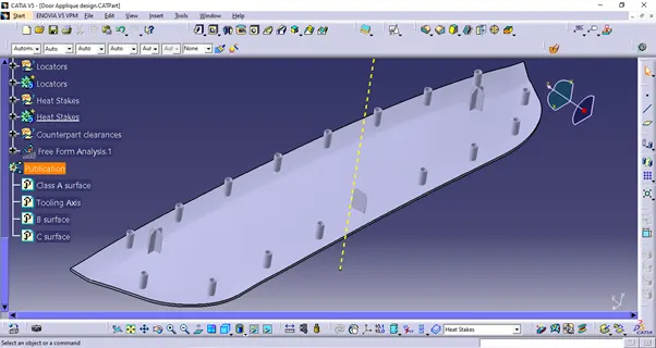
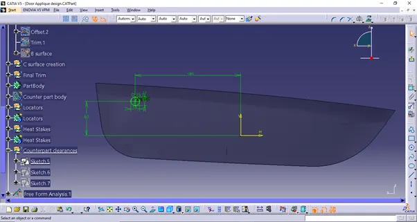
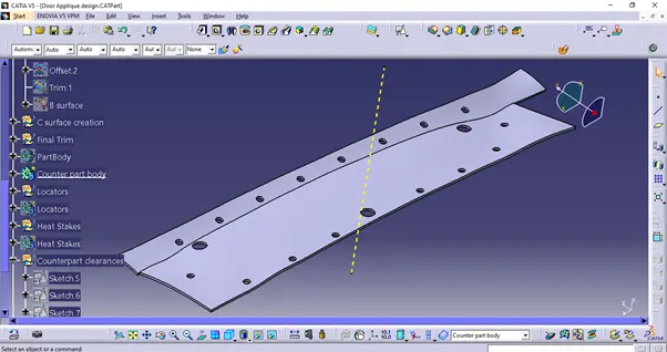
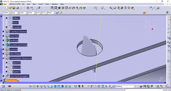
For locators and heat stakes to align with counterpart, holes with clearance needs to be provided on counterpart surface. For this, the counterpart surface is thickened. Then sketches of hole with clearance of 0.1mm for locator and 0.5mm for heat stake are drawn and extruded. These extruded bodies are then removed from counterpart body. The hole body for all heat stakes can be translated similarly as done while translating heat stake.