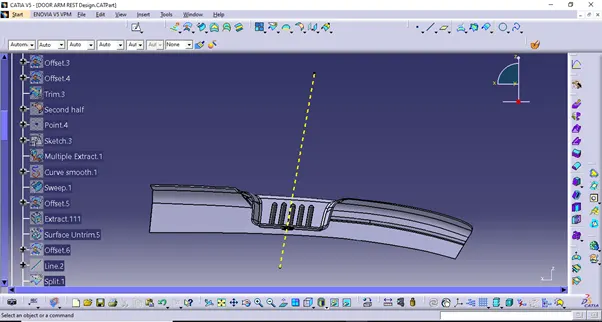
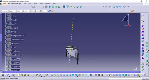
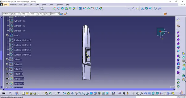
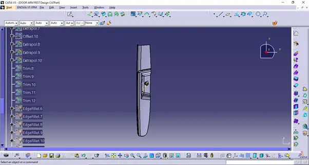
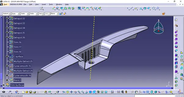
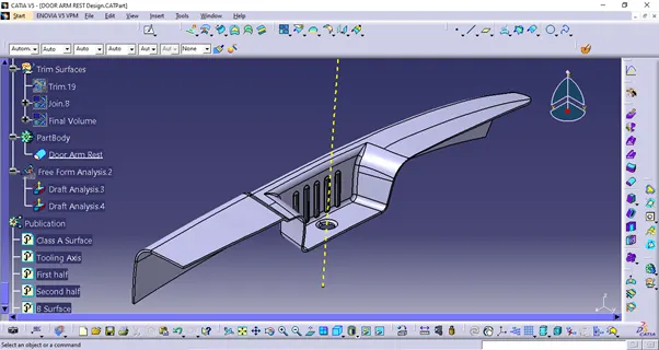
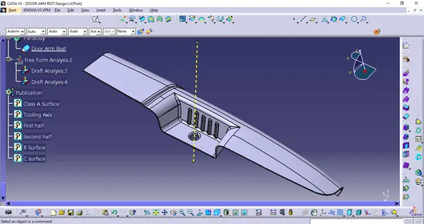
Door Arm Rest design using Catia V5
Aim:
- To design door arm rest from given class A surface by creating tooling axis and class B and C surface.
- Perform draft analysis on the final part.
Design procedure:
- Checking given Class A surface for imperfections.
The imported geometry of class A surface is checked for discontinuities and imperfections. All surfaces are healed and joined together to get single surface body.
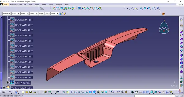
- Tooling axis creation
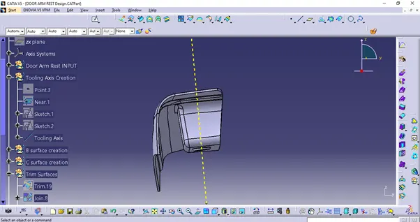
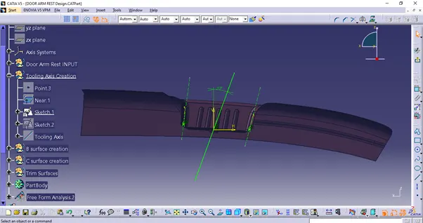
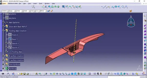
Tooling axis for the component is created using bisecting line method. To get the tooling axis, part is first observed for holes. The holes need to be cleared in the tooling direction itself.
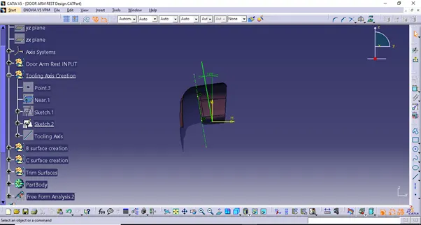
A point is created at the centre of the hole and a new axis system is created by defining the point as origin. The intersection of the component in XZ plane is taken. Two lines which are tangent to the curve side of the component are drawn. Then a bisecting line is created using these two lines which will be considered as tooling axis clearing sides in XZ plane.
The same is done in YZ plane. Since there is only one side in YZ plane, an inclined line is created with that side.
Considering these two axes, a bisecting line is created which is final tooling axis.
- Performing draft analysis using tooling axis
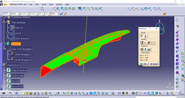
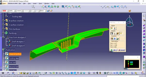
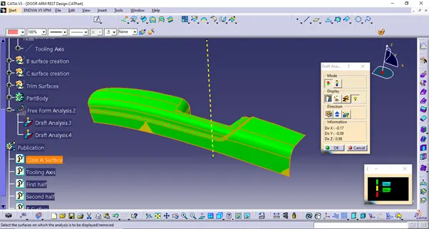
To check if all surfaces are cleared in tooling direction, draft analysis is done. When draft analysis is performed, it was observed that some faces were not under draft condition. So, both tooling axis lines were adjusted by trial-and-error method to get the desired result. After some adjustments, all the surfaces were within draft condition.
- Class B surface creation
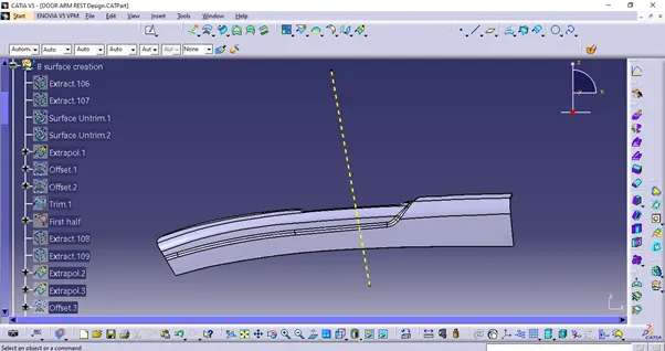
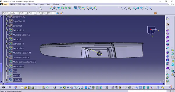
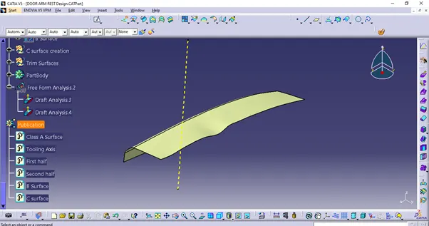
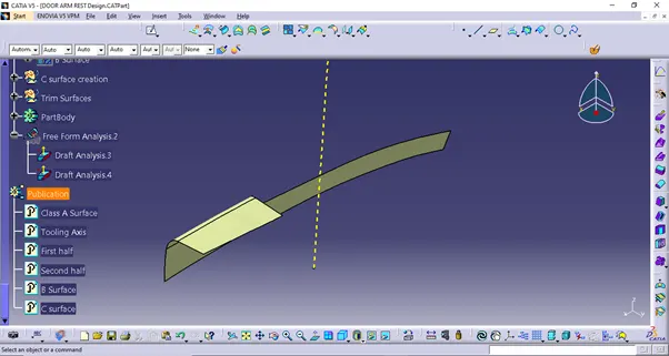
B surface is created by doing extract, untrim, offset and extrapolate operations on each surface separately. Fillet surfaces are not taken in consideration.
For this specific door arm rest design, B surface is created in 3 parts; first half, second half and intersecting surface. All the three parts are created separately and then joined together at intersections by trim option.
- Class C Surface creation
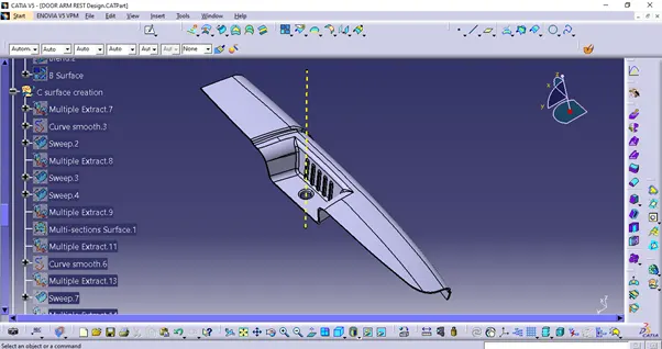
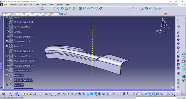
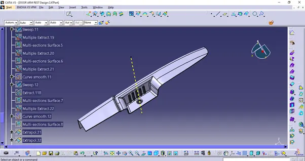
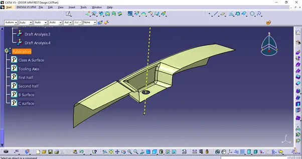
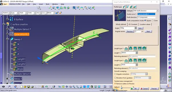
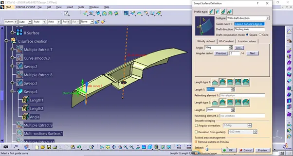
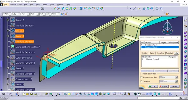
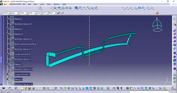
Class C surfaces are created using sweep command. Fillet areas are created using multi section command.
- Creation of final closed volume and converting to solid body
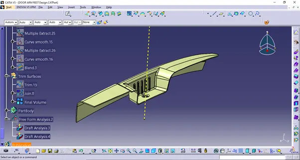
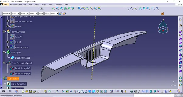
Finally, all the surfaces; class A, B, C are joined together to get the closed volume. This closed volume is then converted to solid body using closed volume command in part design workbench.
- Draft Analysis on the solid body
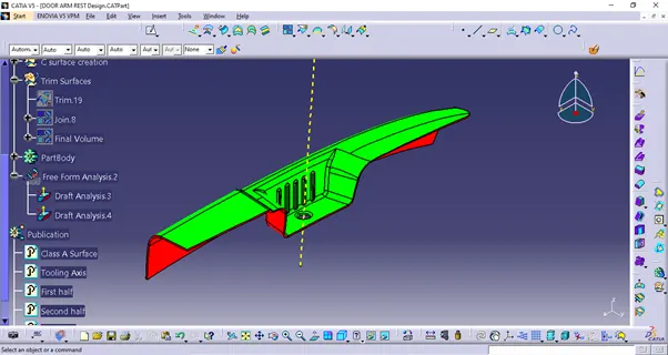
Draft analysis is performed on the final solid body of the door arm rest. In the draft analysis, it was found that all the surfaces meet the draft requirements if the parting line is at the class A surface.