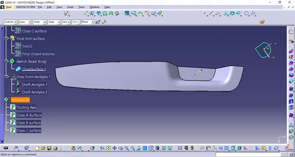
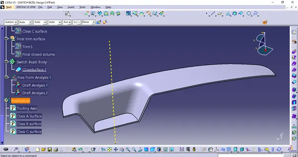
Switch Bezel Plastic Design using Catia V5
Aim: Switch bezel design using given class A surface by creating tooling axis for the component and designing class B and class C surface.
- General considerations:
Minimum draft angle - 3 degrees
The thickness of component – 2.5 mm
- Checking input surface for imperfections.
Given class A surface is first imported and joined as a single surface body.
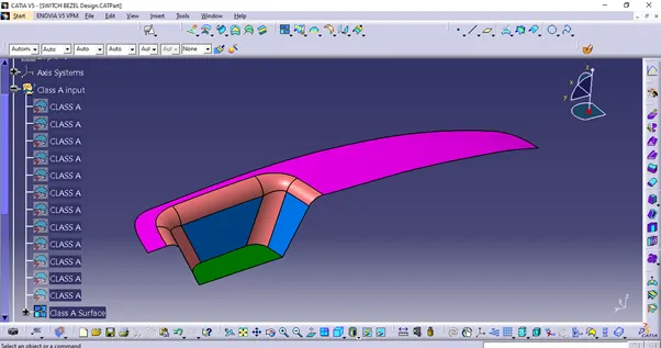
- Tooling axis creation
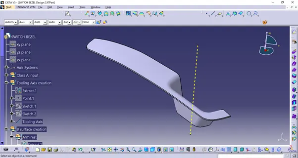
To decide the tooling axis, component is observed for optimum direction. The tooling axis for this component will be created from bisecting line method.
The given component has inclined surfaces in YZ and XZ planes. A point is created at bottom surface and new axis system is created considering the point as origin.
Then intersection of the component with YZ plane is taken. Two lines are drawn on the inclined surfaces and a line bisecting these lines is created. This line will be considered as tooling direction which clears draft faces in YZ plane.
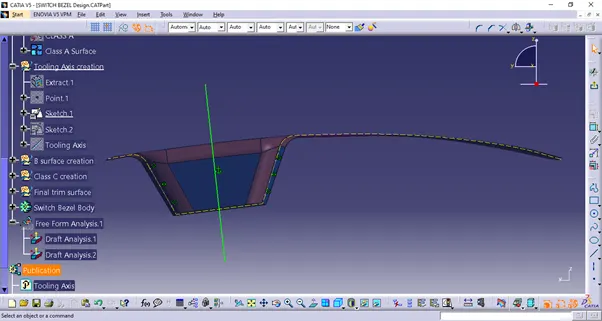
The same is done in XZ plane. Since XZ plane only has one draft surface, a line having an angle of 6 degree with the inclined surface is created. This line is considered as direction clearing sides in XZ plane.
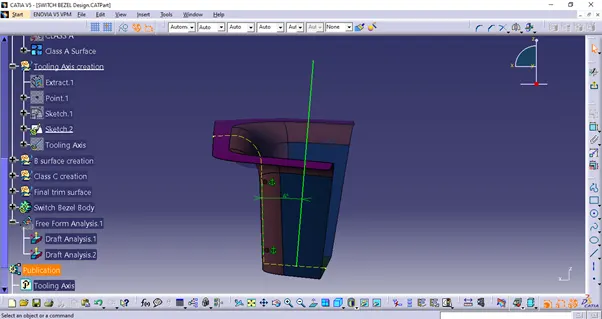
To get the final tooling axis, a bisecting line is drawn from these two tooling clearing directions. This is considered as final tooling axis.
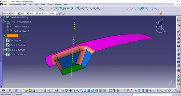
- Draft analysis to check validity of tooling direction.
To check whether the tooling axis created is valid for all surfaces or not, draft analysis is done on class surfaces considering tooling axis as draft direction.
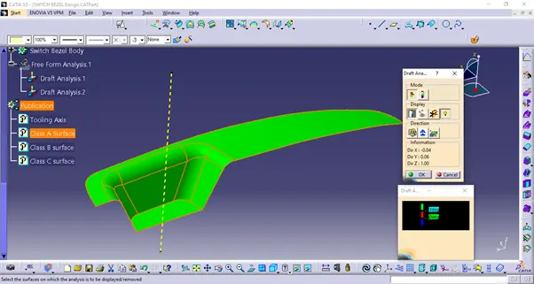
In the draft analysis, it was observed that all surfaces meet the minimum 3-degree draft angle criteria.
- Class B surface creation
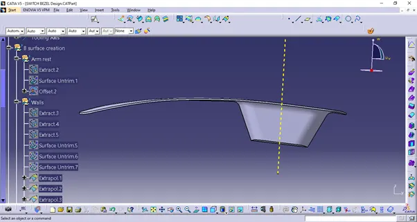
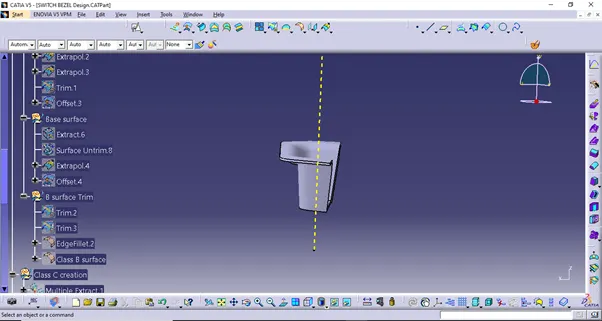
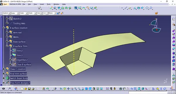
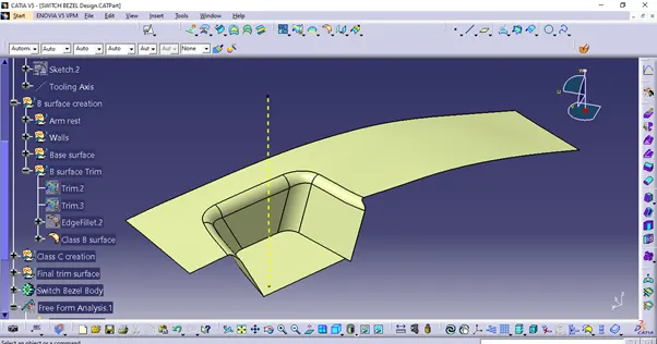
To create class B surface, first the surfaces without fillet are extracted from class A surface. These surfaces are then untrimmed and extrapolated so that they intersect with each other. The thickness of the component is 2.5 mm. Therefore, these surfaces are offset to 2.5 mm.
Then trim operation is performed to get final desired shape. This will be the B surface without any fillets. Fillets are then applied on all edges as per fillet values on class A.
- Class C surface creation
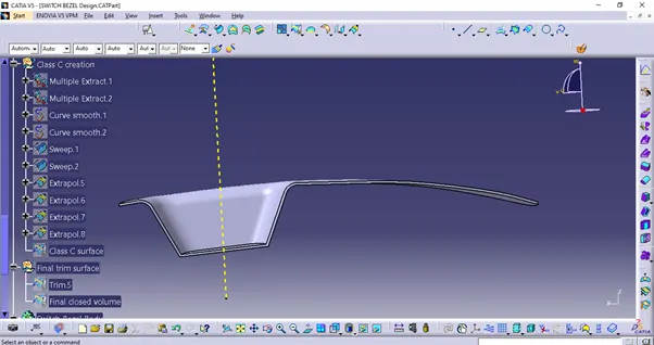
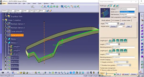
To create Class C surface, the boundary of class A surface is extracted. To avoid irregularity in boundary, smooth curve option is used. This boundary is then swept using sweep with draft direction feature, considering tooling axis as draft direction. 3-degree angle is given to this sweep.
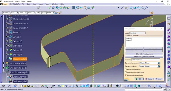
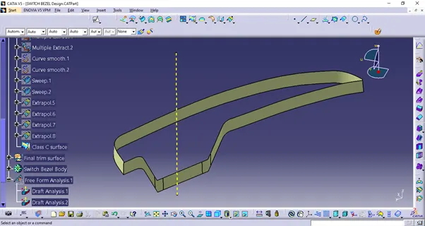
To join all surfaces, discontinuing edges are extrapolated and trimmed to get complete one surface.
- Joining all surfaces to get final volume
The class A, B and C surfaces are then joined to get the final closed volume. Trim and join commands are used to get final volume.
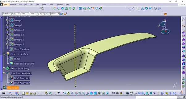
- Creating solid body and performing draft analysis
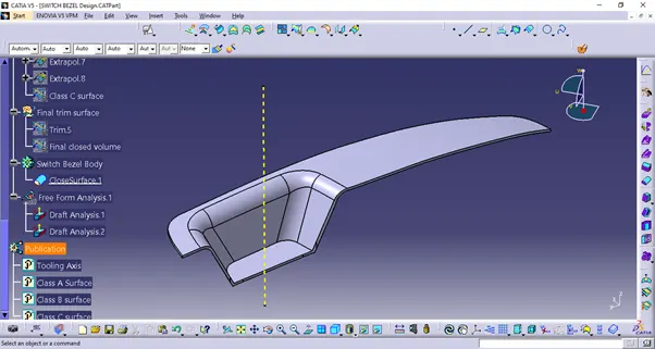
The closed volume is then converted into solid body using closed volume command in part design.
Draft analysis is performed on this solid body to check the manufacturing ability of the component.
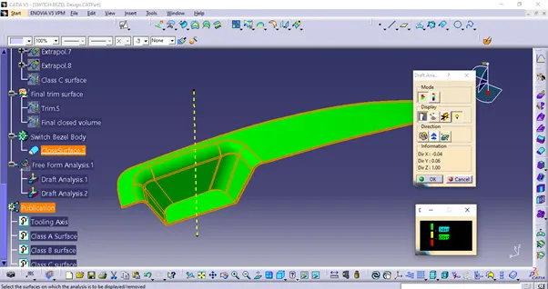
Draft analysis shows that the component satisfies the minimum draft angle requirement. As per scale, surfaces having green colour show the draft angle is more than 3 degrees.