Introduction to BiW and Fixtures
- What is BIW & define its parts?
Ans: In the Automotive Industry BIW (Body in White) is the common terminology used to mention the car sheet metal welded structure (body shell). In today's situation, automotive BIW is made of steel (various steel grade material -DP, DD, HDP etc.) as well as made of aluminium alloy (e.g., AUDI A8).
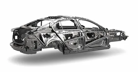
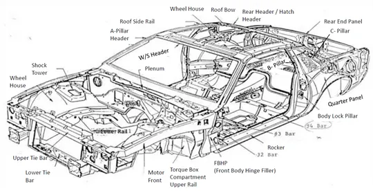
Sub-assemblies like Under body, Body side Left Hand Side/ Right Hand Side, Front End, Roof etc. gets welded together by various metal joining process e.g., resistance spot welding, Laser welding, MIG welding to make welded metal shell (Without Door, Trunk-lid / Tailgate, Fender, Bonnet Centre) called Body in White. Automotive car shell made before painting is called Body in White.
BIW joinery decides the exterior and interior look of any car. All the Interior Parts e.g., Dashboard, Trim (Door Trim, Pillar Trims, Roof liner, Seats are mounted on the BIW shell with the help of various brackets or nuts mounted on the BIW.
Exterior components e.g., Front Bumper, Rear Bumper, Fender LH/RH, Side Mirrors are mounted on the BIW shell with the help of various brackets or mounting systems.
There are two types of BIW:
Monocoque:
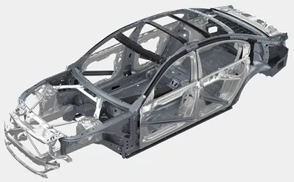
In this type of structure, all the members of the body are load carrying and they are integrated with each other. Here chassis is inbuilt with the BIW itself and there is no separate chassis. Wheels are directly mounted to the BIW with the help of suspension system. Used in all the passenger cars and to some extent in utility vehicles.
Body on frame:
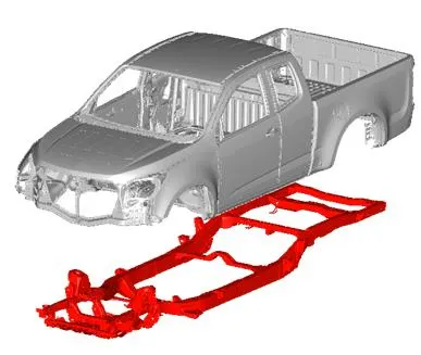
In this type of body construction, the body is placed on frame which is the major load carrying member. Body is mounted on a separate chassis/frame and the wheels are mounted on the chassis and not to the body. Used in utility vehicles, trucks, buses.
BIW Structure can be divided into following sub structures: -
- Under Body Structure
- Front End Structure
- Body Side Structure
- Closures
- Roof
All those substructures consist of the following major panels: -
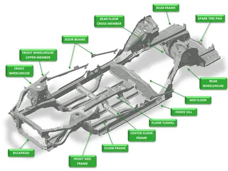
An Under Body Structure: -
- Dash panel-provides partition b/w engine and the driver cabin.
- FRT floor - provides base for seats.
- Raiser - connects front floor to rear floor by providing level difference.
- Rear floor - floor on the rear of the car and provides partition from ground and base for rear seats
- Rear wheel house
Front End Structure: -
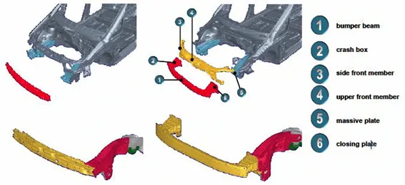
- Plenum Panel- a chamber located b/w the throttle body and runners of the intake manifold.
- FRT wheel house (Fender)- is an encasement around the front wheel.
- Wing panel - outer most side panel in the front.
- Cowl -portion of the body bounded by the front fenders, the base of the windshield, and the rear edge of the hood.
- Upper tie bar -upper panel in front connecting the two sides of front structure.
- Lower tie bar- lower panel in front connecting the two sides of front structure.
Body side Structure: -
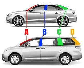
- pillar - front most support to the roof
- pillar - second support to the roof
- C/D pillar - c- is rear most support to roof in case of two row seating system, it will be third one. D- is the fourth support usually rear side of quarter panel.
- Ring panel - a structure panel connecting the rear and front portion.
- Quarter panel - rear most panel of a body side structure.
- Drip rails / Gutters- an exposed channel applied to the roof over the side windows to direct water away from the windows.
Closures: -
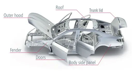
- All doors
- Hoods/Bonnet -a hinged panel providing access to the engine compartment.
Roof Structure: -
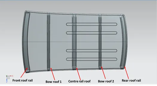
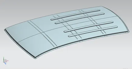
- Roof
- Headers - structural member above the windshield at juncture with the forward edge of the roof panel.
- Bows
2. What do you understand by BIW nomenclature?
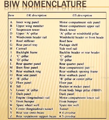
Ans: BIW nomenclature is basically defining a term for specific part. Since, Automotive industries are spread worldwide, different countries use different names for automobile parts. For example, Boot floor panel in UK is referred as rear compartment panel in US.
3. What is fixture & its types?
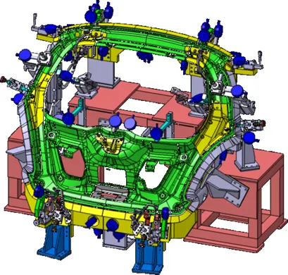
Ans: A BIW fixture is a device that holds the workpiece on which various operations like welding, trimming, etc. are done. This holding or fixing is usually done using 3-2-1 principle.
It is important to hold parts at the proper location to avoid any changes or distortions and maintain proper geometry. Also, clamping force should be such that it will hold the part at required position firmly but should not damage the part with any indentation or scratch marks. The area of clamping should be clear from the welding area and fixture should be rigid and stable enough to withstand welding stresses and any vibrations.
Following are the basic types of BIW fixtures:
- Production Fixtures:
This type of fixture is generally used in mass production. The consistency of production fixtures should be very high, hence the material used for making this fixture is well tested for hardness. Also, its ability to maintain dimensions and tolerances is checked. The production fixture should be made in such a way that maintenance of the same will be easy as it requires maintenance after specific number of operations. To avoid any dwell time, time required for assembly and disassembly of the fixture should be as low as possible.
- Preproduction Operation Fixtures (PPO):
These are prototype fixtures which are designed to check feasibility of the initial batch production and to check for improvements which needs to be implemented before starting actual production. These fixtures can be considered as benchmarks to identify criteria which help us rectify errors. Since this is a prototype fixture, this involves lots of manual operations and a team of expert engineers is required. Cycle time and cost of these type of fixture is high as compared to production fixture.
- Checking Fixtures:
As the name suggests, these fixtures are used for checking and inspection purpose. The gauges are used in these fixtures to check dimensions and tolerances of the part. The measured data is compared with the design data to check if part is ok or not. The geometry of the part is also checked in these fixtures.
4. What is the basic principle of fixture design?
Ans: The basic principle used in fixture design is 3-2-1 principle. Every part has 12 degrees of freedom which are 6 translational and 6 rotational degrees of freedom as shown below.
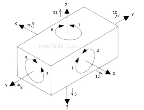
The 3-2-1 principle of location (six-point location principle) is used to constrain the movement of workpiece along the three axes XX, YY, and ZZ. This is achieved by providing six locating points, 3 pins in base plate, 2 pins in vertical plane and 1 pin in a plane which is perpendicular to first two planes.
In this method, 9 degrees of freedom is controlled.
Pins A, B, C on the base plane (a plane parallel to the plane which contains X and Y axis) restrict the rotation of component about X axis and Y axis. It also limits the downward movement of component along z axis. I.e., 1,2,3,4 and 5 degrees of freedom is restricted.
Pins D, E is in plane parallel to the plane containing X and Z axes. It prevents the rotation of component about Z axis (6, 7 degree of freedom) and the movement of the body in along Y axis towards one direction (8 degree of freedom).
The last pin F is in a plane parallel to plane contains Y and Z axes. It restricts the movement component along X axis in one direction.
Three remaining degree of freedom 10, 11, 12 is unrestricted. It facilitates the loading of the component in the fixture. These three degrees of freedom may restrict after loading of component by using clamping devices.
5. Elaborate types of BIW Stations?
Ans: The complete BIW assembly line is divided in various zones and these zones are divided into stations. These BIW Stations can be further divided as:
- Tool Stations
- Gripper Stations
- Stand Station
- Miscellaneous Stations
1] Tool stations:
a. Geo Fixtures:
- In geo fixture, tack welding is done for all the parts to be assembled in that fixture. The geo fixture defines the geometry of the part.
- All the parts must be located with the help of locating pins.
- These have tight accuracy standards. For geo fixture, all the machine parts individually should be made with maximum tolerance of ± 0.02mm, whereas Pin tolerance should be -0.15mm.
- In geo fixture, welding is done in such a way that the geometric accuracy of the assembly is achieved and it will not vary while handling or moving from one station to another.
b. Re-Spot Fixtures:
- In Re-spot fixture, secondary weld points are welded.
- In an assembly, if there are considerably high number of weld points, then the primary weld points which will define the geometry with more accuracy will be welded in geo fixture and remaining secondary points will be covered in Re-spot fixtures. Due to this no station will be ideal.
c. Marriage Fixture:
- As the name suggests, assembly of parts is done this type of fixture.
- All final parts will come to this station and will be assembled using joining techniques like hemming, gluing, riveting etc.
d. Framer Fixture:
- Framer fixture is next station after marriage fixture.
- In framer fixture, roof is attached to output of marriage fixture and it forms frame like structure, hence it is called framer fixture.
e. Checking Fixture:
- These fixtures are used to check the assembly of parts, tolerance, dimensions and coordinates.
- It can be gauge type, fixed type or automated checking fixture.
- In this fixture, work piece is held and different measuring gauges are used to check dimensions of the work piece.
- In a fixed type, workpiece is fixed with clamps and CMM is used to measure predefined coordinates of different parts in assembly.
2] Grippers:
A gripper is device which hold the workpiece. A gripper can be attached to robot or can be part of a fixed automation system.
Different types of grippers are as follows:
a. Material handling gripper:
As the name suggest, these grippers are used to pick assembly from one station and will drop an assembly to another station.
b. Process grippers:
- These grippers are used to carry out some specific process like gluing, welding, riveting etc. in addition with material handling.
c. Combo Gripper:
- Combo grippers are the one which can carry out multiple tasks like it can do material handling and also can carry out some specific process like gluing, welding etc.
d. Dual Gripper:
- These are two sided grippers. These are used for handling of symmetric parts like doors. It carries parts from one station to another.
3) Stands:
Stands are used to hold parts for storage or to perform operation on part. Different stands in BIW are as follows:
a. Pedestal stands:
- Weld gun is mounted on the fixed stand which is mounted to the floor permanently. The gripper can carry the panel under the stand to perform the operation.
b. Gluing or Sealer stand:
- Gluing gun or sealer gun is fixed to a stand which is fastened to the floor permanently.
c. Docking Stand:
- The robots have some limitations such as payload capacity or lack of space.
- In this case, we add docking stand to put some equipment which is not in use for current operation but will be required for next operation.
- Hence the robot can drop a gripper gun and pick next operation equipment to complete the task from docking stand.
d.Date stamp stand:
- Every manufactured product has some data to stamped or embossed on it like number, date etc. for future reference. This data is stamped on product by stamping device mounted on stamp stand.
4) Miscellaneous stand:
a) Curing: After gluing part needs some time to cool down, so we put assembly on some belts and it will take the panel to another station and meanwhile gluing will cool down.
b) Buffer stand: After the operations are completed, we can put assemblies in this stand which is buffer stock and can be transported from one station to another easily. They are also used as inventory when machines are undergoing maintenance.
c) Take out trolleys: It is used to take out some panels for inspection and to examine if the process is going on right or not between the cycle.
d) Conveyor: Conveyor is the rotating path which transports the parts to the next station which are kept over it.
6. What are the basic terminologies used in the BIW fixture?
Ans: The following terminologies are used in BIW
- NC/Mylars/Fingers: Mylar are the components which hold the panel while operation is going on. These are placed from top side and from bottom side. The top side are called clamping mylars whereas bottom side are called resting mylars. Mylars don’t allow deformation of the part due to welding stresses.
- Principal Locating Point (PLP): These are the points which are used for the accurate location of the part to maintain the geometry of the assembly. There are lots of holes on the panel which are not accurate due to stamping operation. The PLP are defined in the drawing. The positional dimensions or relative dimensions are very precise in stamping and in fixtures also.
- Risers: Risers are of different type like L-type risers, square tube riser etc. Riser is the manufacturing part which gives height to the assemblies.
- Blade: Blades are the plates mounted on the riser. Other parts like cylinder, arms are mounted on the blade.
- Shims: Shims are the small parts which comes with the thickness of 0.1mm, 0.2mm, 0.5mm, etc. These will compensate the stack up tolerance which reflects at the panel holding part called Mylars. We give tolerance to all parts of the fixture. Due to these tolerances, mylars will either lift up or goes down from its defined height and will make impression or dent on the panel. So, to adjust mylars at proper position shims are used.
- Rough locators: The operator can place the part in wrong orientation by mistake. The rough locator will work as guide while placing the part in the fixture and the part will be loaded in desired orientation.
- Hardwares: Hardwares are Hex head bolts, Allen bolts, Hex nuts, spring washers etc used in BIW fixtures.
- CMM: CMM stands for coordinate measuring machine. It is a device that measures the geometry of physical objects by sensing discrete points on the surface of the object with a probe. The generated report is then compared with the CAD data.
- Unit: The fixture is the assembly of different types of units to form fixture. There are different units like pin unit, base unit, clamping unit etc.
- Number plates: Number plate is the aluminium embossed plate on each unit for easy recognition of unit.
- Name plate: The data like manufacturing company name, fixture type, fixture weight etc is embossed on the plate and joined to the fixture.
- Clamp Arm: Clamp arm is the part of the clamp unit which moves over an axis. Mylars are mounted on clamp arm.
- Pivot: It is an axis about which the clamp arm will rotate.
- Class A surface/Skin surface: The outer panels of the car like hood, door, fender, roof, etc. are visible to the customer. These should be aesthetically good and should not be damaged or scratched in fixtures. These are called Class A or Skin surfaces.
- Reed Switches and sensors: These are electric components used in automated fixtures. The reed switch is an electrical switch operated by an applied magnetic field. These detects if panels are loaded or not by using sensors.