Modelling, Assembly and rendering of Yacht
Modelling and Rendering of Sunseeker Predator Yacht
- Introduction:
During this project, modelling of different parts of the yacht will be done, then assembly of Yacht and rendering of the model will be done to get photorealistic images of assembly model.
- Objective:
The objective of the project is to design and model parts of sunseeker predator yacht and then assembly of the same to get photorealistic render images of yacht. During modelling of yacht, various features will be discovered to design complex parts.
- Design methodology:
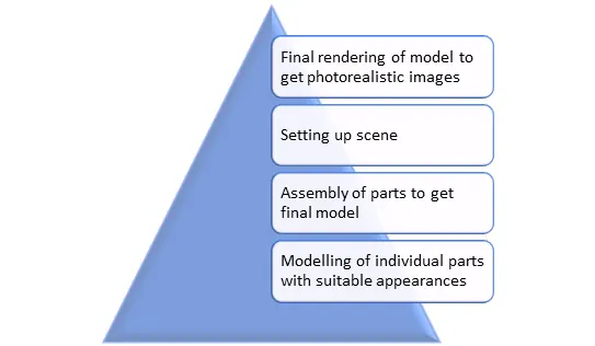
For this project, we will be using a bottom-up design approach. First modelling of separate parts will be done. Then appearances will be given to each part individually. After that, assembly of the parts will be done to get the final complete model of Sunseeker predator yacht. Then scene setup will be done to get the perfect environment. Final rendering will be done in photo view 360 to get the photorealistic images of final product.
- Modelling of individual parts.
Sunseeker Predator Yacht assembly contains following parts:
- Propeller
- Radar
- Hull
- Garage Door
- Front Seat
- Middle Seat
- Rear Seat
- Superstructure
- Radar Mast
- Propeller
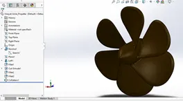
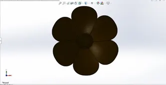
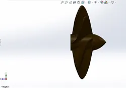
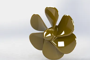
Propeller is a rotor fixed at back of yacht which helps yacht to move by converting its rotational power in linear thrust on water.
Design procedure and features used:
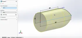
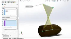
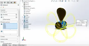
The main features used in modelling of propeller are Boss revolve, Loft, cut extrude, fillet and circular pattern.
The main hub of propeller is modelled using revolve feature with sketch of the profile of hub. Then loft feature is used to create the blade of rotor. Fillet option is used to shape the blades and smoothen sharp edges. Cut extrude feature is used to cut a hole on hub to fix propeller with shaft. Custom colour appearance is given to propeller.
b. Radar
Radar is placed on top point of yacht to determine nearby ships and velocity with the use of radio waves.
Design procedure and features used:
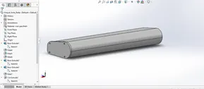
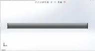
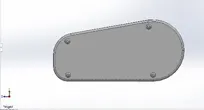
The main features used in Radar modelling are Boss extrude, cut extrude, fillet, mirror and split line.
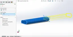
The main body is modelled using boss extrude feature, first half of the radar is modelled and the mirrored to get complete body of radar. Various holes at the required positions are cut with help of cut extrude feature. All the sharp edges are treated with fillet.
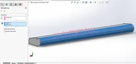
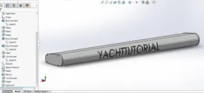
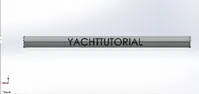
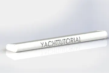
A text of the name is created on the radar body with the help of split line feature.
c. Hull
Hull is the main body of the ship on which all the components will be fixed.
Design procedure and features used:
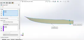
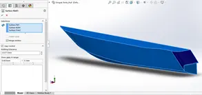
The main features used in modelling of hull is surface extrude, loft surface, boundary surface, extend surface, ruled surface.
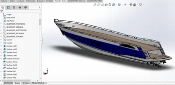
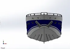
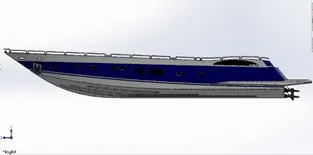
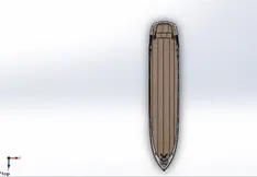
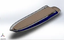
First the blueprints of all views are set into environment. Then with the reference of blueprint all the surfaces of the body are generated. Complete Hull is modelled using surfacing approach. Then the complete body is converted into single solid body by knitting all the surfaces together. The additional accessories are added on the hull body with the help of boss extrude, cut extrude, boss revolve, sweep boss commands. Also, helix command is used along with sweep command to get rope body.
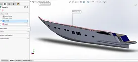
Projected curve option is used to get the curves for railings and different surface bodies. Split line option is used to create strip appearance on outer side of body.
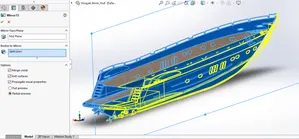
Save bodies option is used when garage space was cut out from main body. This body will be used to create garage door. Floor decals are used on floor and stairs to add appearance of floor on hull surface. Another surface is created by offsetting the hull floor. Offset distance is kept zero and the surface is hidden in part. In this way, we get a surface body at the place of hull floor which will be used as reference for seat modelling.
d. Garage door
As name suggests, it is a openable door for garage where all the vehicles of the passengers will be parked.
Design procedure and features used:
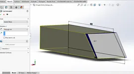
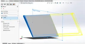
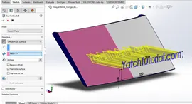
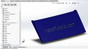
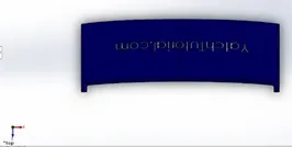
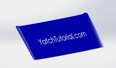
The features used are mainly cut extrude, fillet shell and mirror. The saved body of garage is renamed as garage door. The part of door is cut from the body and shell feature is used to make it like a door. Since it is the only half body, other half is mirrored to get full body. All the sharp edges are treated with fillet. Text is created on a separate plane and it is cut on door body to give it an aesthetic look.
e. Front seat
f. Middle seat
g. Rear Seat
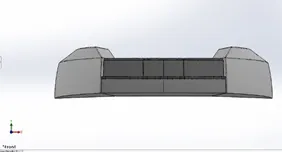
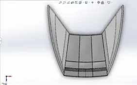
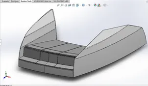
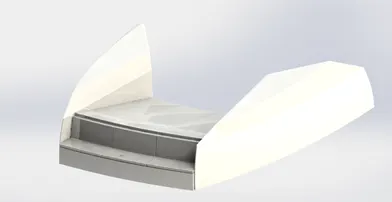
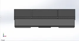
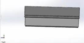
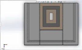
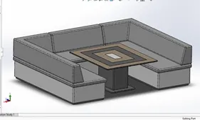
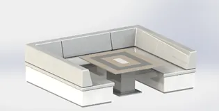
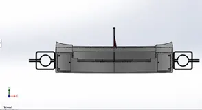
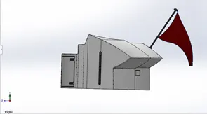
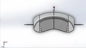
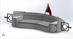
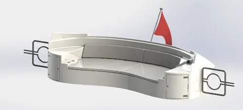
These are the seating arrangements made at the front, middle and rear side of the yacht respectively.
Design procedure and features used:
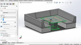
The main features used in modelling of seating arrangement are lofted surface, extrude surface, surface sweep, revolve, cut extrude, boss extrude and fillet.
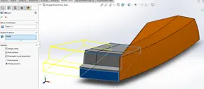
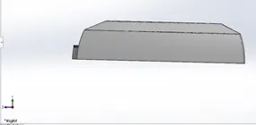
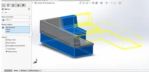
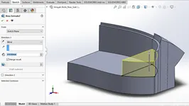
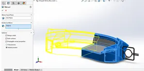
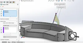
First import part option is used and only surface body from the Hull part is imported for reference. All the surfaces of the seats are generated with the reference of blueprints. For all seating arrangements, firstly half part is modelled using surface modelling. Then the half body is mirrored and converted into solid body. To generate pillows, offset surface feature is used. All the sharp edges are treated with fillet. Dome feature is used to give curvature to pillow surfaces. The Flag on the rear seat is created using surface loft feature. Four 3D sketches of spline are used to create boundaries of flag.
h. Superstructure
Superstructure is an upward extension above hull surface. In this case, inside superstructure rooms and other amenities are provided.
Design procedure and features used:
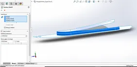
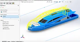
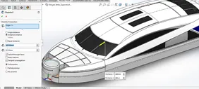
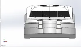
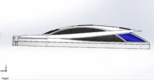
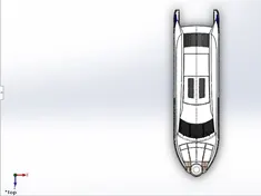
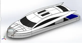
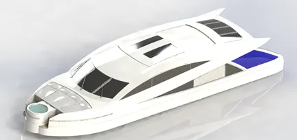
The Superstructure is modelled the same way as Hull is modelled by generating surfaces from blueprint references. First Hull surface body is imported and, on this body, superstructure is modelled. Main features used in modelling and surface modelling features like surface extrude, extend surface, lofted surface etc. Projected curves are used to get different profiles of surfaces. First half is modelled using surface modelling and then second half is mirrored. Resulting body is converted into solid body. Boss extrude, cut extrude features are used for detailing work on body.
One offset surface is generated at the top of the structure with offset distance zero. This result in a separate surface body which will be used as reference in radar mast modelling.
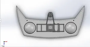
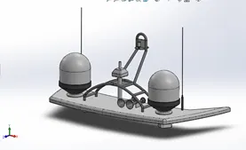
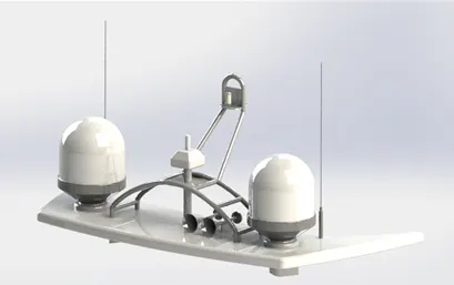
i. Radar Mast
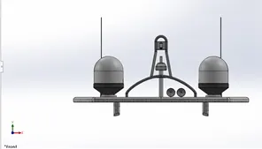
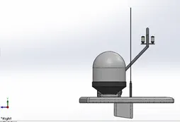
Radar Mast is fixture located on top of superstructure on which radar is fitted. Radar mast contains antennas which collect data for radar.
Design procedure and features used:
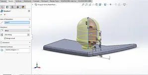
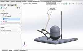
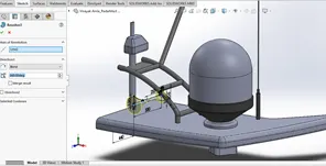
For modelling of radar mast, insert part option is used. Then only surface body from superstructure is imported for refernce. Radar mast is modelled using slid modelling features like revolve boss, boss extrude, cut extrude etc.
Only half part of radar mast is modelled and then mirrored to get complete body. Projected curve is used to sweep the pipe bodies. Dome feature is used to give curvature on horn surface. Also, shell feature is used to get hollow horn body. Chamfer feature is used to get tapered surfaces. All sharp edges are treated with fillet.
2. Assembly of parts.
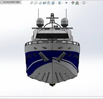
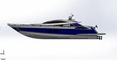
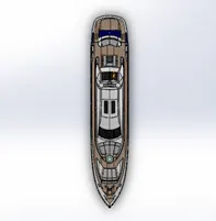
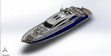
All the parts of the yacht are assembled in an assembly file. While doing assembly, first all the parts are brought into an assembly file. Hull, superstructure, radar mast, front and middle seat are directly fixed in assembly as they have reference surfaces in common. Other parts are treated with manual mates.
The various mates used are as Coincident, concentric, parallel, distance etc. These mates are applied to respective faces, edges and surfaces and planes.
3. Setting up scene.
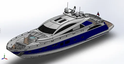
For setting up scene, various pre-set scenes can be used which are available in solid works. Other values like brightness, environment, shadows can be adjusted in edit scene tab. Multiple lights can be setup as per requirements. Cameras can be added to get a view of a specific angle while rendering.
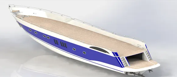
Below is the example of a Yacht model set up in a 3-point faded scene available in solid works.
4. Final Rendering of Assembly.
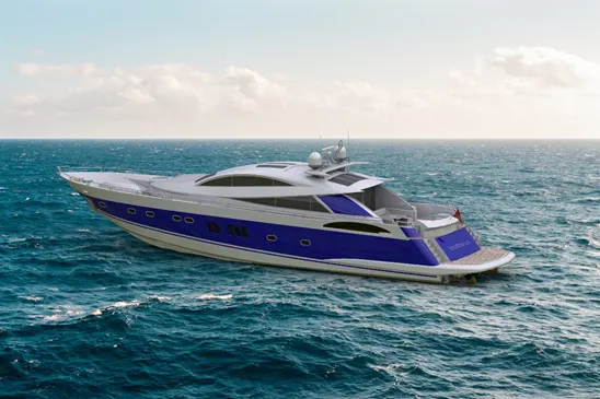
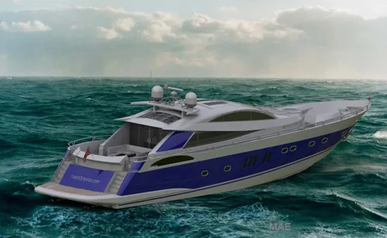
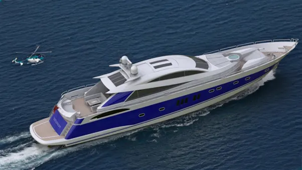
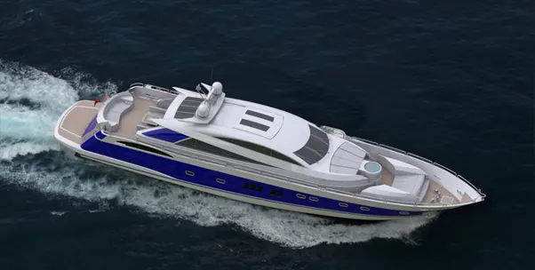
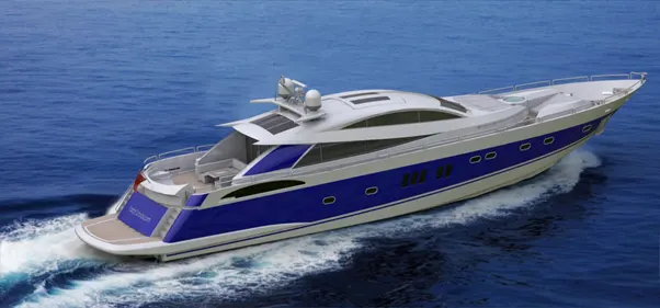
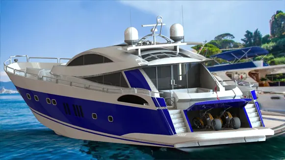
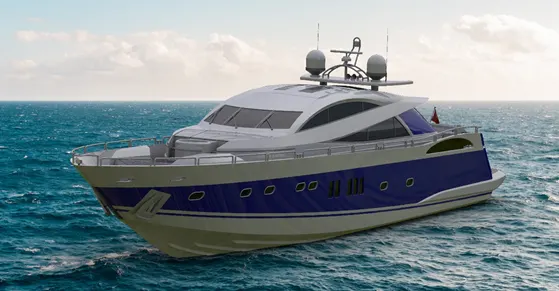
Rendering is a process of generating photo realistic images of model. Rendered images is a simulation of model is real world. This can be done using various software and tools. The tool mainly used here is Photo view 360.
- Conclusion:
During this project, various surface modelling techniques were discovered and learned achieve surface continuity while converting surface bodies to solid bodies.
Also, setting up scene for rendering of photorealistic images for presentation or display purpose was learned during this project.