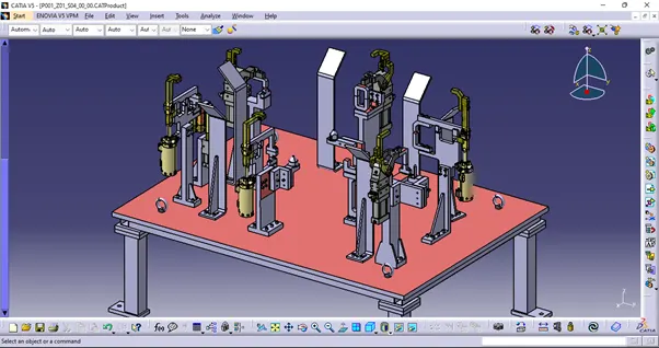
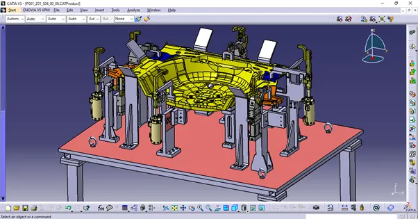
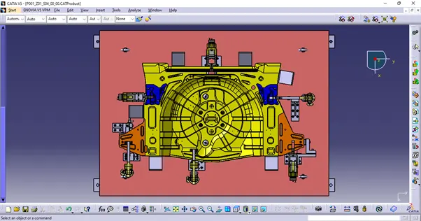
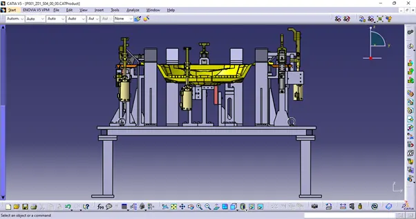
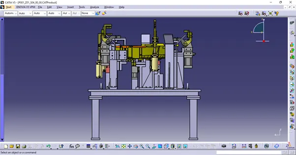
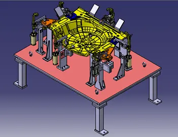
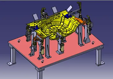
3D Finishing on Fixture Assembly
Aim: To perform a 3D finish and create rough locators for the given panel assembly design.
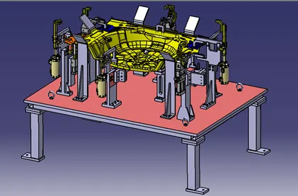
3D finishing Process:
- The 3D finish is a process where the design is finished and ready for final simulation and 2D detailing.
- The nominalism of the designed parts is checked to ease the assembly of all the units. The concentricity of all holes is checked to ensure the assembly of parts.
- Various gaps in the parts of the units are checked to ensure proper working of the units. To guide panel in proper orientation on the fixture, rough locators are designed. This will ensure that panel is loaded in required orientation.
- To ensure that the weld gun does not collide with any of the units during the welding process, gun study is done. Pneumatic layout is designed for all pneumatic connections for actuation of cylinders.
- Sensors and Solenoid valves are selected as per the requirement of the units.
- Fasteners are implemented as per hole size. Standard colour coding is applied according to standards to differentiate the type of hole, whether dowel, threaded, etc.
- All the parts in the assembly are renamed so that each part can be differentiated as unique.
- After this 3D finish process is done, sent for simulation and 2D detailing.
The following points need to be taken care of while finishing the design:
- Hole concentricity and hole sizes:
For ease of assembly of units, concentricity and size of holes are checked.
- Machining area:
Only required part of the surface should be machined to reduce cost and save time. The machining area in every part is defined in 3D finishing using standard colour code. Machining is done on parts to properly mount with mating parts.
- Nominality:
The dimensions of all units are kept nominal for easy manufacturing and assembly.
- Holes colouring standard;
The holes are provided with specific colours to identify whether the hole is dowel hole or threaded hole etc. According to some common standards, dowel hole is given blue colour, the threaded hole is given yellow colour, while open or counter bore holes are given cyan colour.
- Pneumatic Lay-outing:
Pneumatic lay-outing is done to prepare a layout of all pneumatic pipes which will supply the air from inlet to the different cylinders. It should be done properly to ensure proper working of units.
- Gaps Checking:
The gaps between all parts are checked and made flush if required for proper working of the units.
- Fasteners implementation:
Fasteners should be implemented as per the functional and load requirements of the assembly.
- Avoid clash between different parts:
A proper gap should be maintained between units to avoid clashes between units.
- Mylars splitting as per panel profile:
Mylars splitting as per panel profile should be confirmed before finishing design.
- Proper naming of parts and assemblies as per standards:
Proper naming of parts and assemblies as per standards should be done to identify the individual part belonging to the respective assembly.
Rough Locators:
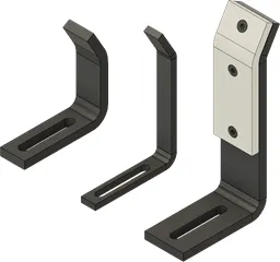
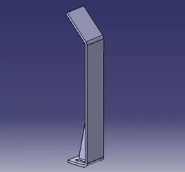
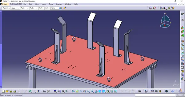
- A rough locator is a part designed to guide the panel in position and to locate car panel on the pins accordingly. A rough locator can be standard or make part.
- Rough locators also work as Poka-Yoke. Poka-Yoke is a Japanese concept used for mistake-proofing.
- Rough locators are used to helping locate workpieces in the automation process. Locating refers to the desired location where you want the workpiece to be when it is getting worked on either by a person, team, or robot.
- The accuracy of the locating components directly affects the consistency and how the final product will come out.
- It can also be called a foolproofing method. The rough locators are set according to the angle of the respective panel and hence the part can be loaded in a defined direction and orientation only.
The following points are needed to be taken into consideration while designing a rough locator:
- A rough locator has to be placed at the edges of the panel, which it has to guide.
- A locator has to be placed at the same angle as the angle of car panel edge, with a minimum distance of 2 to 5mm from the edge of car panel.
- The rough locator should guide the panel in pin arresting location.
- The rough locator should start guiding the panel 10 to 15mm before the start of pin engagement.
- The applicator should be designed with an entry angle for car panel which generally ranges in 30 to 45 degrees.
- A rough locator should be designed with two slots at base for mounting and adjusting the locator on the base.
- The slot provided should be in the direction of car panel guiding.
3D finishing process on design:
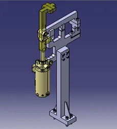
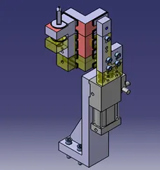
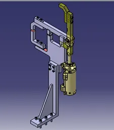
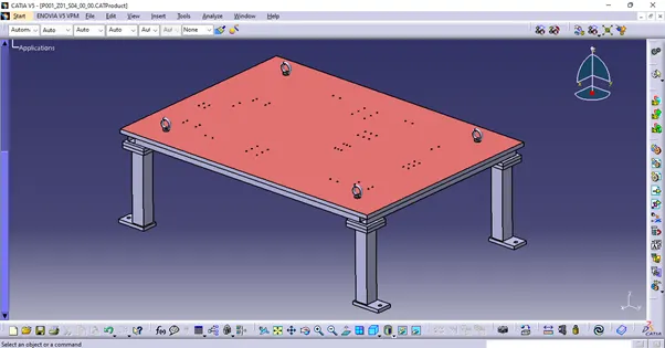
- All the units are made nominal with respect to base unit. The pin units can not be made nominal as the coordinates of hole and pin should match. Hence, only clamp units are made nominal. All parts in the unit are made of nominal sizes.
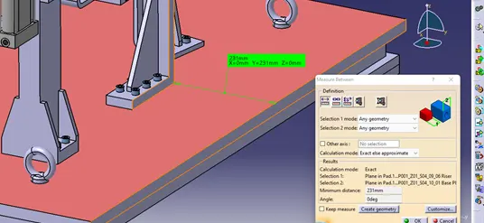
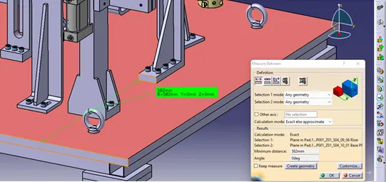
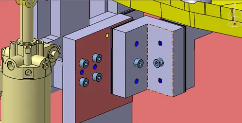
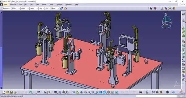
- All Holes are given colour code as per the standards. Threaded holes are given yellow colour, dowel holes as blue and open holes are given cyan colour. Surface which requires machining for finish are given in light brown colour.
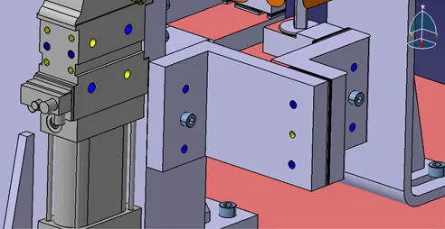
- Rough locators are created to guide the panel onto the fixture.
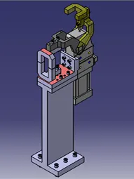
Clamp units, Pin units, and Rest unit:
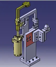
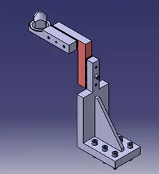
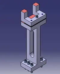
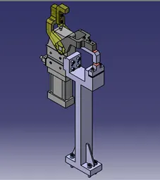
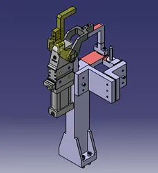
Base Unit:
Rough Locators:
Final Assembly: