Week 8 - Challenge 2 - Switch Bezel Design
Title: SWITCH BEZEL
Aim: To create a switch bezel Plastic Component through a given Class A Surface and perform Draft Analysis on the final plastic component
Objectives:
- Creation of Tooling Axis.
- Creation of Class B and Class C surface.
- Creating a solid part out of surface modelling.
- Draft Analysis of Class A surface and final plastic component.
Tool Used: CATIA V5
Introduction: In this project we are designing a base bracket using given class A surface. The approach includes creation of Class B surface keeping 3 mm thickness in mind for the complete component. The design also included Class C creation from the given parent surface.
Constraints:
- NO CHANGES IN CLASS A ARE ALLOWED.
- PART THICKNESS CANT DEVIATE BY MORE THAN ±">±±30%
- ALL DESIGN RULES SHOULD BE STRICTLY FOLLOWED.
- ALL SURFACES SHOULD BE CLOSED BEFORE CONVERTING TO SOLID.
- ALL FACES SHOULD MEET THE ALLOWED DRAFT REQUIREMENTS.
DRAFT ANALYSIS:
The Draft Analysis allows the user to easily analyze a part for proper draft angle. A Draft Angle describes the amount of taper for molded or cast parts perpendicular to the parting line. Find the Draft Analysis in Tools tab. Draft Analysis is applicable for 3D part models.
CLASS A: Following surface is given as the input for the component creation.
What is the class-A surface?
Class ‘A’ surfaces are primarily used in the automotive environment and refer to those surfaces which are visible in a product. In other words: A - class surfaces are those aesthetic/free-form surfaces, which are visible to us (interior/exterior), and have an optimal aesthetic shape and high surface quality.
Here, one should understand the difference between the internal or external and visible or hidden surface. The surfaces or regions which are visible nowadays are considered for Class-A modelling. It is one of the reasons why the importance of Class-A modelling is increasing day by day. Majority of the time this term is used in Plastic Part designs.
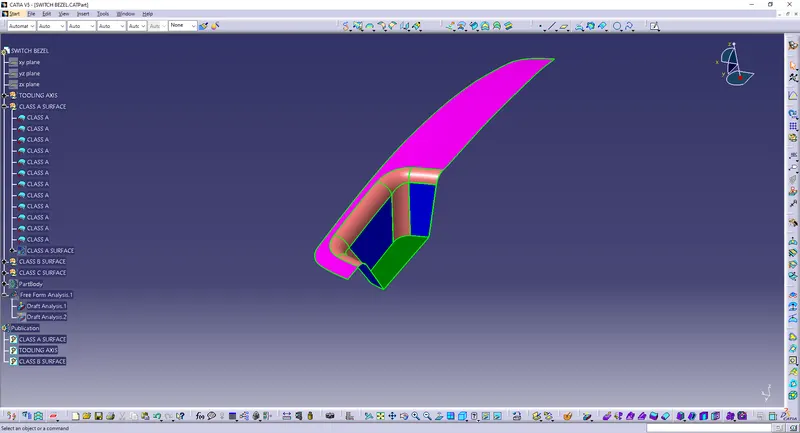
To continue with the design process first we need to find out the tooling axis for the surface and check for all the drafts using Draft Analysis tool of CATIA.
Draft Analysis for Surface A:
The analysis is done for 3degree draft. So as can be seen all the surfaces are more than 3deg.
Creating of Tooling Axis:
- Create an intersection of CLASS A surface with ZX plane and from the intersection create the tooling axis as shown below.
-
A) TOOLING AXIS CREATION:
- Create a point on class A surface with the aim to move the main tool for component creation
- .
- Mask an axis over the point created with the same directions as the main axis
 .
.- Using Intersect command from Generative Shape design select the YZ plane as the first element and the class A surface as the second element
 .
.- After creating the intersecting lines select the Line command and join the vertices which show the most possible draft angle manufacturable and bisect those two lines over the axis point we selected at the first

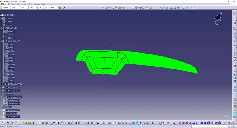
- TOOLING AXIS IS TWO METHOD
BISECTING
NORMAL TO SURFACE
I follow in normal to surface Refer to circle and after create in point in mid cicrle and line devolped in z axis an they analysis in class a surface.
Here, Line shown in dotted pink is our tooling axis.
Creation of Class B:
- Now for Class B creation, we have extracted surface from Class A and untrimmed them to obtain the original parent surface.
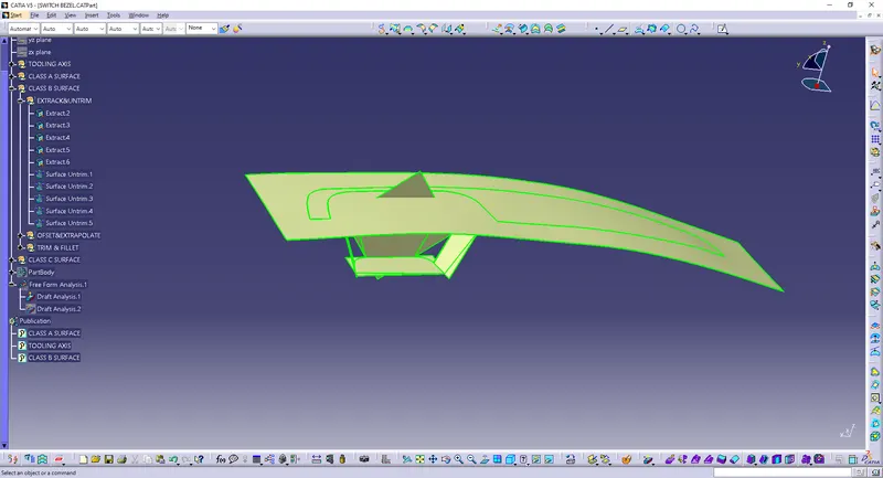
- These surfaces are then offset to the required thickness.
- After offsetting, all the surfaces are trimmed into the required shape
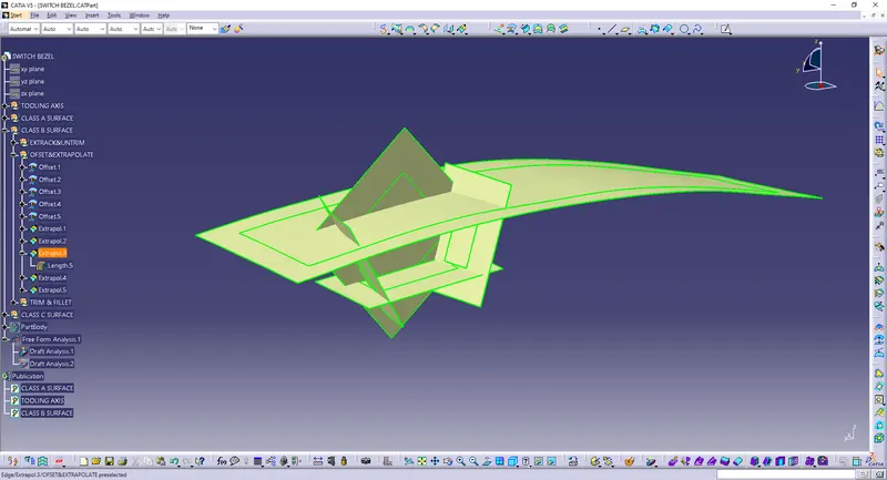
- Class B: The Class B finish is a quality finish with only minimal imperfections. A Class B finish is the most common finish for exterior surfaces. It is normally specified on surfaces such as external covers, panels, and parts that are fairly prominent.
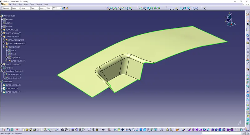
- Required fillets are given to the surfaces.
Creation of Class C:
- For creating this surface we have extracted the boundry of Class A using multi-extract and then converted to smooth curve.
-
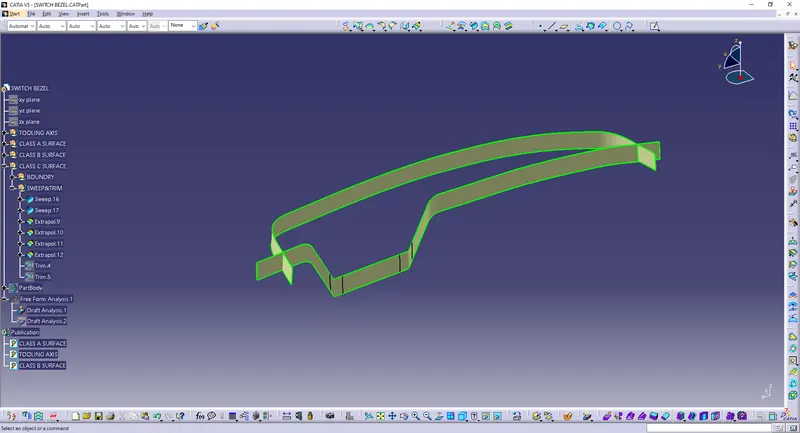
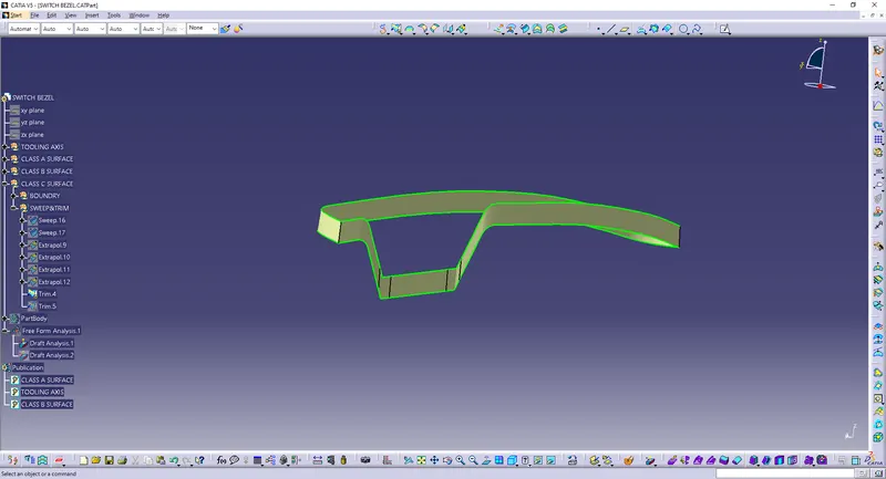
- Now this smooth curve is swept along the draft direction with a 3deg draft.
Final Trims:
Class A Class C and Class :
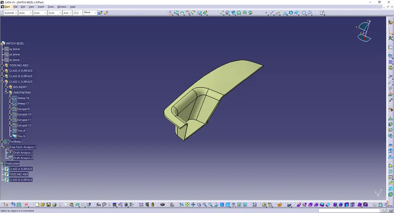
To make sure that there is not any open boundry between class A and class C, we have used join option to created the single body. This is done to make sure that the parting line doesn't lie between the these two surfaces.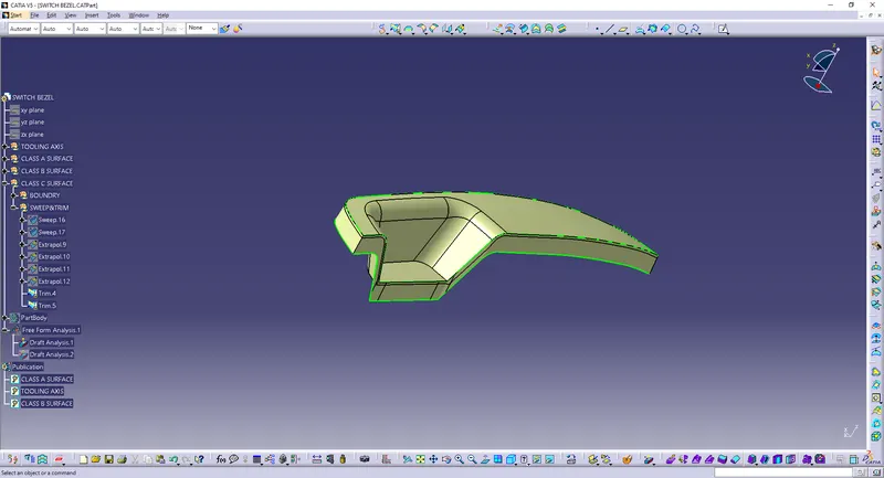
For this we have trimmed the above shown surface with the Class B surface using trim feature.
All the main features are published as can be seen in the image shown above.
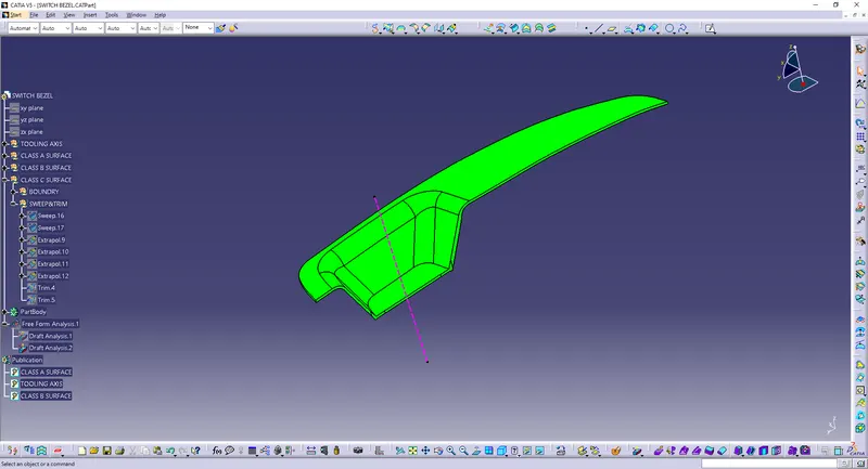
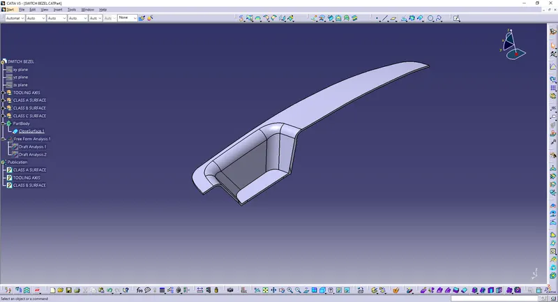
Draft Analysis on the Final Component:
For this analysis, main tooling axis is taken draft reference.
Following results were obtained:
MATERIAL CHOSE:
Polyester is a category of polymers that contain the ester functional group in every repeat unit of their main chain.[1] As a specific material, it most commonly refers to a type called polyethylene terephthalate (PET). Polyesters include naturally occurring chemicals, such as in plants and insects, as well as synthetics such as polybutyrate. Natural polyesters and a few synthetic ones are biodegradable, but most synthetic polyesters are not. Synthetic polyesters are used extensively in clothing.
What are the Uses of Polyester?
- Polyesters are widely used in clothing fabrics. Several types of clothing apparel are woven from polyester yarns or polyester threads. ...
- Polyester is also employed in the manufacture of many home furnishing materials such as bedsheets, curtains, blankets, and pillowcases.
- Polyester is also used in upholstered furniture.
- Another important application of this polymer is in the manufacture of mouse pads.
CONCLUSION:-
Finally the Class – A, B&C surfaces with the Tooling Direction have been Published and the Switch Bezel is moved on to the designing of the next operation – the creation of B-side features.