Week 8 - Challenge 2 - Switch Bezel Design
Report
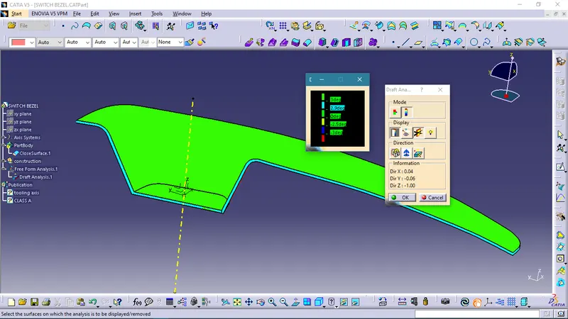
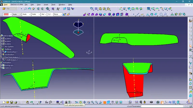
The tooling axis was created using sketches of lines based on the geometry of the Class A surface. The A surface has three vertical wall faces which are almost vertical to the Z axis. In order to select the Z axis as the general direction of tooling, based on the geometry of class A, the tooling axis must be at an angle to the Z component such that all 3 wall faces are at an angle above 3 degrees to it, which is the minimum draft angle. To obtain this, one line was drawn with reference from the two opposite walls and one from the third wall being at an angle greater than 3 degrees from the Z axis. The resulting bisecting line was chosen as the tooling axis based on draft analysis on the class A surface.
Draft Analysis on Class A input :
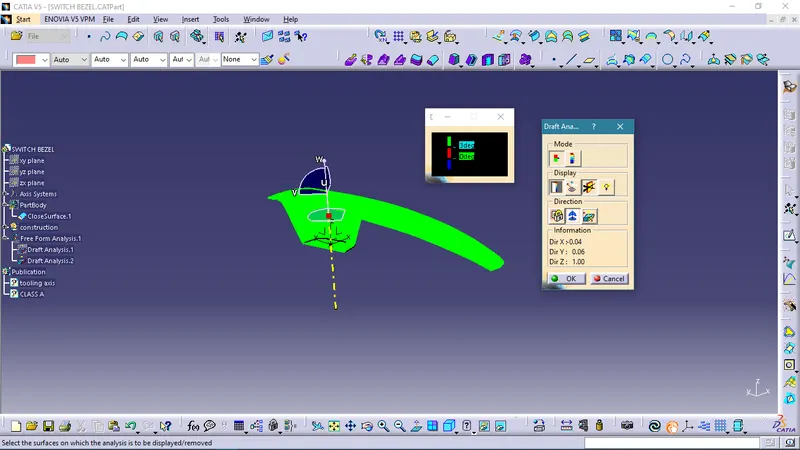
Draft Analysis of the final component :