Week 8 - Challenge 1 - Base Bracket Design
AIM: to make a model from the provided class-A surface.
INTRODUCTION:
CLASS-A SURFACE: a surface made by the designer which is given as an input to the plastic modeler to work on. It is aesthetic surface and the outer most surface.
CLASS-B SURFACE: a surface below a certain thickness from the class-A surface is class-B surface. This is the surface that contains engineering aspects of a model.
CLASS-C SURFACE: a surface that joins class-A and class-B surfaces is class-C surface.
MATERIAL USED : THERMOSET PLASTIC
PROPERTIES OF THERMOSET PLASTIC:
ADVANTAGES: More resistance against high temprature, hard and rigid, excellent aesthetics finishes, high mechanical property
DISADVANTAGES: cannot be recycled, cannot be remolder or reshaped
METHODOLOGY:
In this model we have focused on the following things:
- save part in (CATpart.) format
- Tooling axis
- Draft analysis A & fianl product
- Class-B surface
- Class-C surface
- Making a solid model from surface.
Following tools were used to reach the final step:
- Extract
- Un-trim
- Trim
- Extrapolate
- Offset
- Edge fillet
- Boundary
- Sweep
- Join
- Close (part design)
FOR TOOLING AXIS:
- First ensure the class-A surface is properly joined and has no discontinuity on it. For this we can use boundary command or join command.
- Analyze the model manually or visually to see which direction is most suitable for tooling axis.
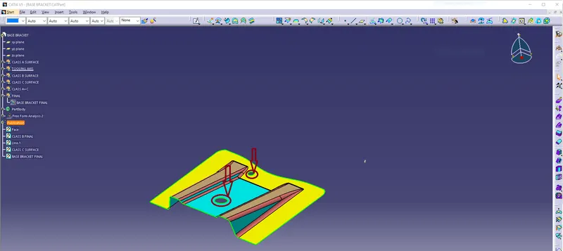
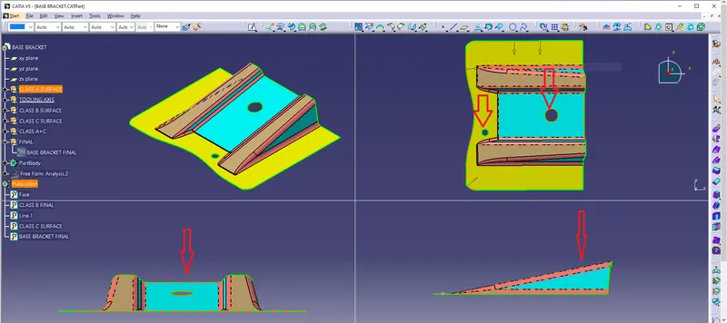
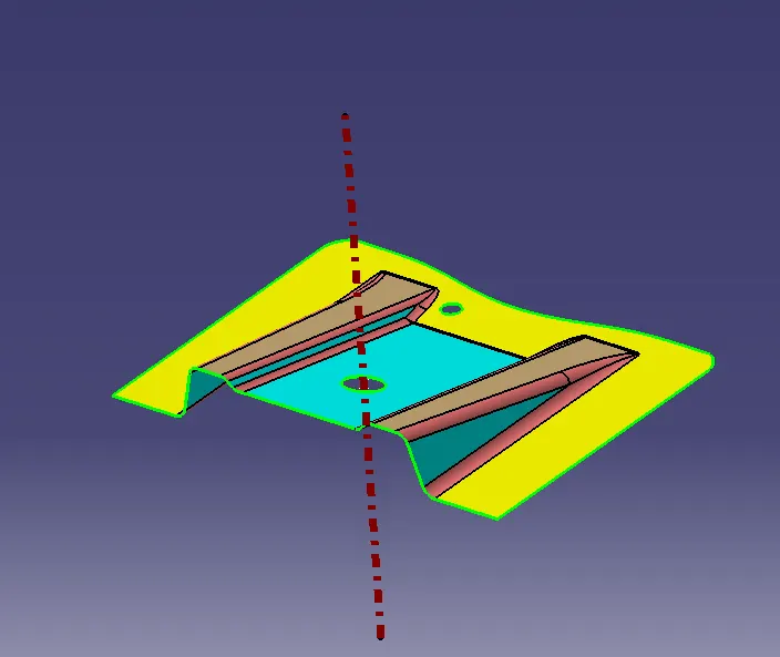
- As in 3D view, we can see 2 holes and a flat surface, we can directly take the tooling axis perpendicular to that. But to be sure, let us analyze from all the views. The below images of the front side and top views shows the areas that we have to keep in mind while choosing tooling axis. As from X we cannot see one hole so we cannot take axis along this. In Y we cannot see any holes so here too we cannot take tooling axis. But in Z we can see 2 holes and flat surface so we can take tooling axis.
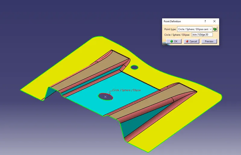
- Create the tooling axis to the selected view. create the centre pont in the hole using the point defination.
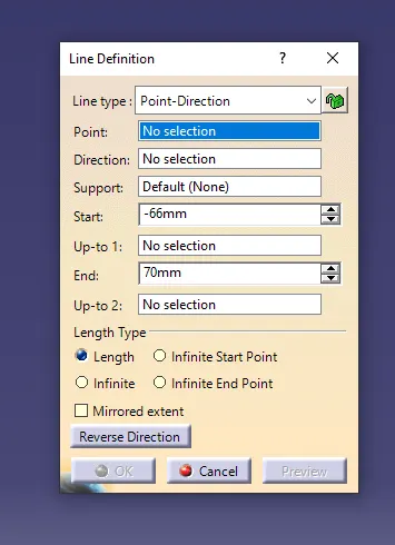
- Click the line command and open window in line difenation. click the option point and direction. select the point and select the direction in Z- direction.the axis line is generated then change the name of line to TOOL AXIS.
FOR DRAFT ANALYSIS:
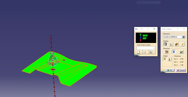
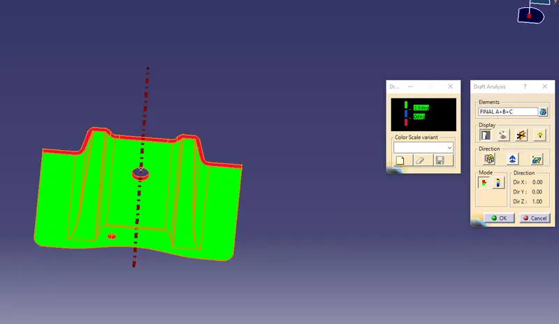
- Go to insert< analysis< feature draft analysis.
- Align the tooling axis with the compass.
- Click on the surface and see that the surface is within the permissible limit of the draft values.
- The surface should be green and in the column proper value (2.5deg) should be inserted.
FOR CLASS-B SURFACE:
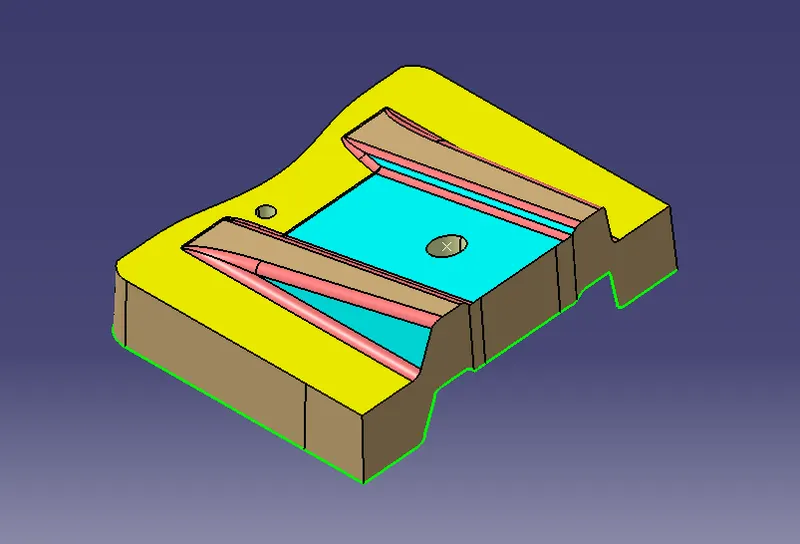
We can divide the surfaces as shown below. Then we will work on them one by one.
FLAT SURFACE:
- Extract the flat surface.
- Un-trim the surface.
- Extrapolate it.
- Offset it by 2.5mm i.e. thickness.
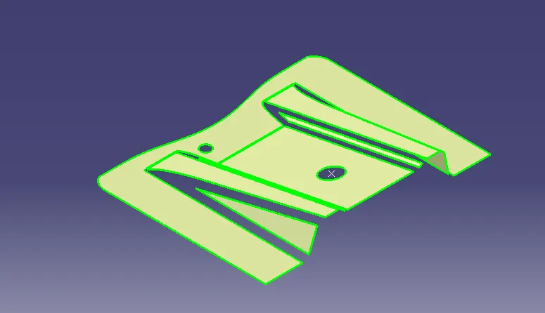
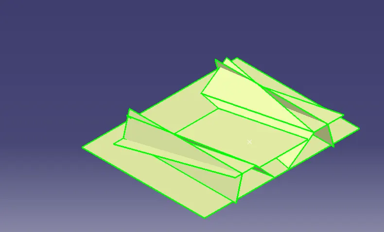
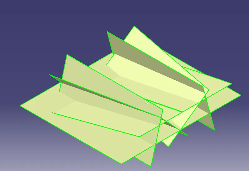
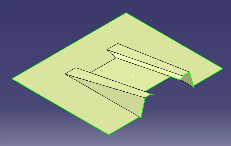
After 2.5mm offset the trimmed surface in direct oppsite downward of CLASS A surface.
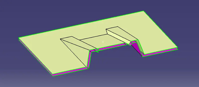
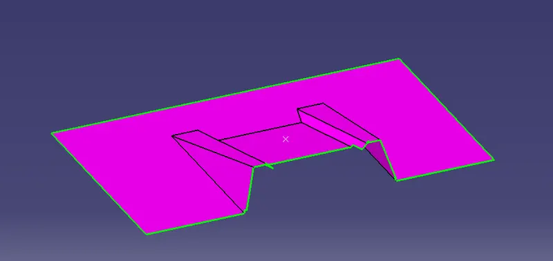
Finally the CLASS B surface is crated and published. Then hide the CLASS B surface.
FOR CLASS-C SURFACE:
- Extract the boundary of the class-A surface.
- Extract the boundary of the holes on the class-A surface.
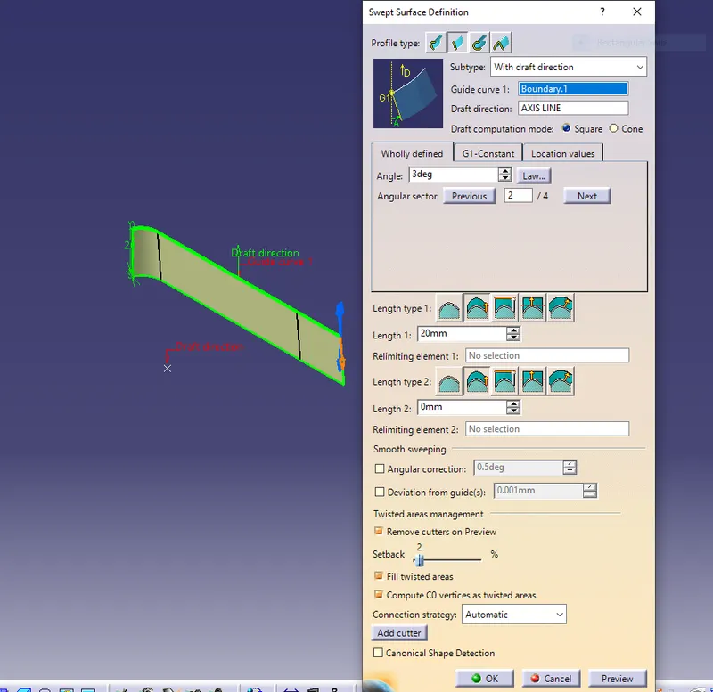
- Use sweep command on the boundaries one by one to get the class-C surface.
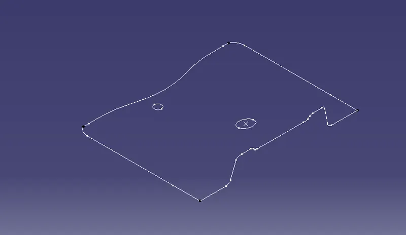
To unhide the surafce A and select the boundary command.then select the boundary in A surafe. after creating boundary there is multi points are created so select the smoothen curve command select the boundaryes and change to smooth curves.
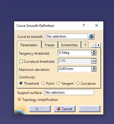
select the continuity in : curvature
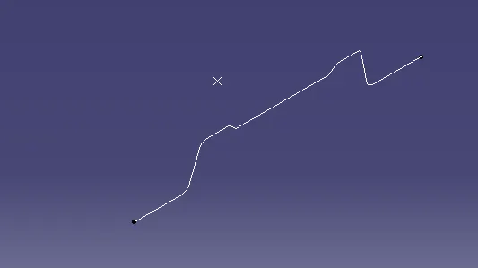
Select the swept command. option click line and > sub system is with a draft direction and select the guid curve 1 in > click the boundary > draft direction selecct the AXIS LINE> give the draft value in 3 deg >
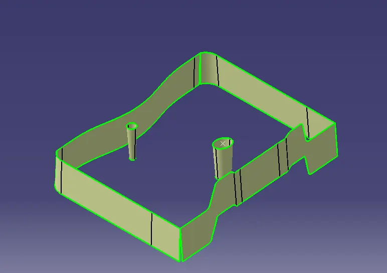
Then extraploate the cannot intersection surface. and do trim. The complete class C surface is done.
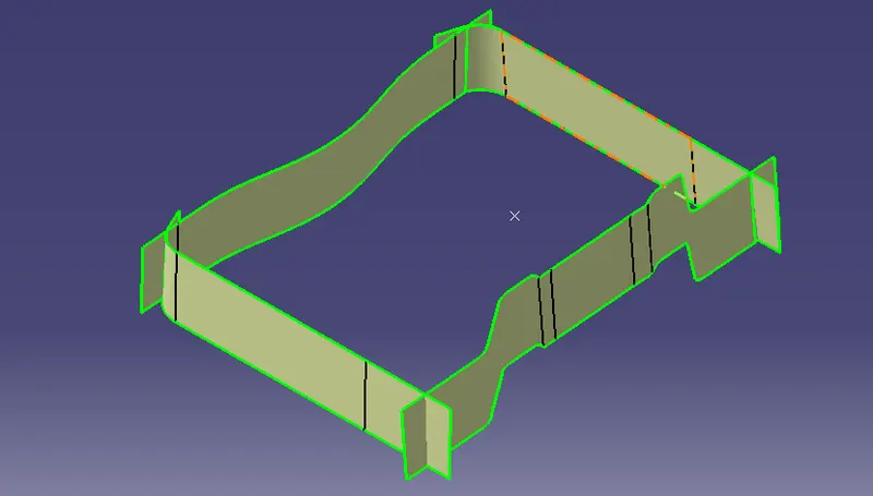
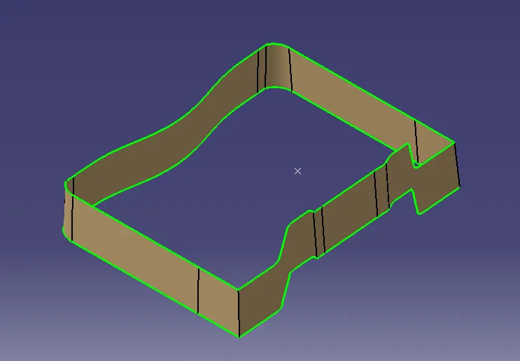
FINAL BASE BRACKET:
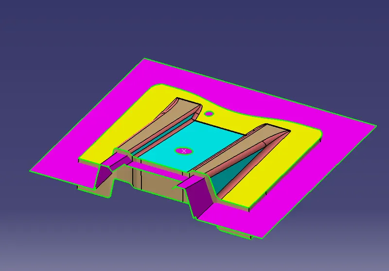
- Join the class-A and class-C surfaces together.
- Trim the class-B surface with the join created earlier.
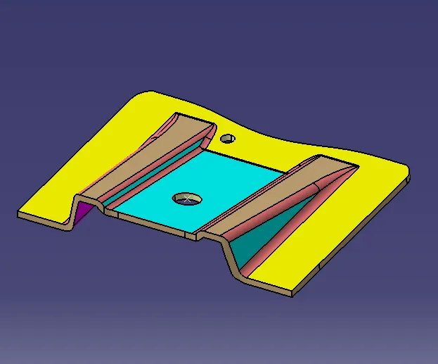
- Go to part design and close the model.
DRAFT ANALYSIS
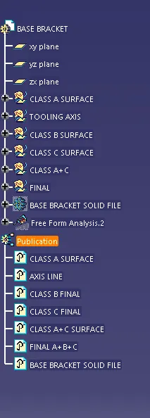
TREE STRUCTURE: