Week 8 - Challenge 4 - Bumper
AIM
Create the Bumper Plastic component through the given Class-A surface. To begin with, the tooling axis for the given Class-A Surface should be created meeting the requirements of the draft angle and at the end perform the Draft analysis on the model.
INTRODUCTION
A bumper is a structure attached to or integrated with the front and rear ends of a motor vehicle, to absorb impact in a minor collision, ideally minimizing repair costs.
MATERIAL : (ABS)
ABS stands for Acrylonitrile Butadiene Styrene. ABS is an impact-resistant engineering thermoplastic & amorphous polymer. ABS is made up of three monomers: acrylonitrile, butadiene and styrene:
- Acrylonitrile: It is a synthetic monomer produced from propylene and ammonia. This component contributes to ABS chemical resistance & heat stability
- Butadiene: It is produced as a by-product of ethylene production from steam crackers. This component delivers toughness & impact strength to ABS polymer
- Styrene: It is manufactured by dehydrogenation of ethyl benzene. It provides rigidity & processability to ABS plastic
ABS offers a good balance of impact, heat, chemical and abrasion resistance, dimensional stability, tensile strength, surface hardness, rigidity and electrical characteristics. ABS plastic remains hard, rigid and tough even at low temperatures. It is available in fire-retardant, heat-resistant and platable grades
- Injection Molding
- Pre-drying is not always needed for injection molding with a vented cylinder. In case drying is needed then 4 hours at 80°C is generally sufficient. Signs of moisture are stripes, streaks or bubbles in the molding and if any of these are seen then the material should be pre-dried
- Melt temperature: 210-270°C
- Mold temperature: of 40-70°C
- Material Injection Pressure: 50 - 100 MPa
- Injection Speed: Moderate - High
- Extrusion
- Pre-Drying: 3 hours at 70-80°C
- Extrusion temperature: 210 to 240°C
- Screw Design: L/D ratio of 25-30 is recommended
- MECHANICAL PROPERTIES OF ABS
| Elongation at Break | 10 - 50 % |
| Elongation at Yield | 1.7 - 6 % |
| Flexibility (Flexural Modulus) | 1.6 - 2.4 GPa |
| Hardness Shore D | 100 |
| Stiffness (Flexural Modulus) | 1.6 - 2.4 GPa |
| Strength at Break (Tensile) | 29.8 - 43 MPa |
| Strength at Yield (Tensile) | 29.6 - 48 MPa |
| Toughness (Notched Izod Impact at Room Temperature) | 200 - 215 J/m |
| Toughness at Low Temperature (Notched Izod Impact at Low Temperature) | 20 - 160 J/m |
| Young Modulus | 1.79 - 3.2 GPa |
OBJECTIVE
- To design Bumper as per automotive industry Standard.
- Create tooling axis for the given CLASS-A surface.
- Create B Class and C Class surfaces
- Create final surface model and convert it into solid body using close surface command in the part design workbench.
- Perform draft analysis for both Class-A surface and Final part body.
Class A Surface is
- Visible surface and aesthetic look.
- Surface with textures.
- Surfaces provided by customer(OEM).
- Don't have any features like(rib, snap, bosses, etc) on class A surface.
- Class A surface is made from scanned data with different software like alias etc.
- Surfaces which are having CURVATURE CONTINUITY IS CALLED class-A.
Class B surface is
- Invisible Surfaces.
- Surface mostly don't have textures.
- Surface needs to be created according to the class-A surface.
- Having all features(Rib,boss,snap etc) in B-side surface only.
- Surfaces which is having TANGENT CONTINUITY IS CALLED class-B.
Class A Surface : Check the connectivity of the Class A Surface Ensure that there is no gap between the component, using join command. We can visually check it or by clicking boundary command. It has a boundaries outer. Therefore first check completed.
Class-A surface means visible surface. It gives the aesthetic of the component which is created by the styling team and gives to the part design engineer to create the part with all engineering aspects.
The first step is to check the continuity of the class A surface. This is to ensure that there is no gap between surfaces. If we find any then we should fix that first.
Class-A continuity check
Analyse the class A surface through visual inspection.
To make sure that the given surface has no gap in between them. We can check it also with the help of Join or boundary commands.
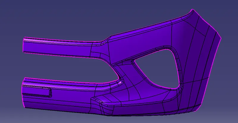
Procedure :
Tooling Direction for Plastic Part : Tooling direction is main consideration for plastic part and mold parts because it defines movement of mold part and possibility of plastic part to come-out from mold part (Core and Cavity).
- In Molding machine arrangement is given to open the mold along a direction which is known as Tooling Direction.
- In other words. The mold is built from two separate halves (Core and Cavity) and tooling direction basically define the direction of mold pulls apart.
- Tooling direction is known as primary direction.
Preparation of Tooling Direction
While creating the tooling direction in given class A surface. Chose the one suitable Base and Side wall and draw the line direction of axis
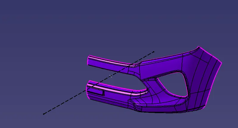
Draft analysis for the given CLASS-A surface.
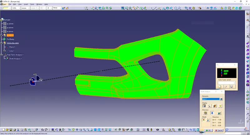
The Draft Analysis is a command enables you to detect if the part you drafted will be easily removed. This type of analysis is performed based on colour ranges identifying zones on the analysed element where the deviation from the draft direction at any point, corresponds to specified values.
Draft analysis is done after determining the tooling axis, draft analysis is used to check whether the minimum draft (3 degrees) is maintained or not.
- Procedure for performing the draft analysis are as follows
- Change the view mode of the component to be in customized parameter mode and then select the shading mode as materials.
- Then open the featured draft analysis tool from the insert menu.
- Then click on use the compass to define the current drafting direction and then drag and align the compass on the Tooling axis.
- Then lock the draft direction and perform draft analysis by clicking on the component.
-
- The green colour shows the positive daft tooling direction and the given surface passes the draft analysis.
- Click on the analyses under the running point to check the draft analysis on the individual faces. It shows how much draft on specific points when we move the cursor point.
-
SURFACE-B CREATION
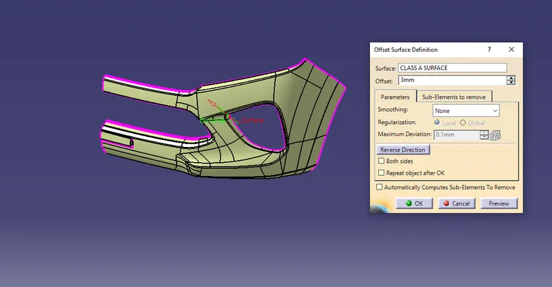
Class-B surface means thickness of a part it is not visible and is inside part. In other words, Class-B surface is a surface below a certain thickness from the class-A surface. This is the surface that contains engineering aspects of a model.
- Offset the class-A surface to 3mm inward direction.
- Rework on the patches and discontinuity of the offset surfaces using the features like extract, multi-extract, sweep, multi-section surfaces, extrapolate.
- To ensure the continuity of the Class-B surfaces check the boundary command to find out the boundary.
- Hence class-B surface creation is done.
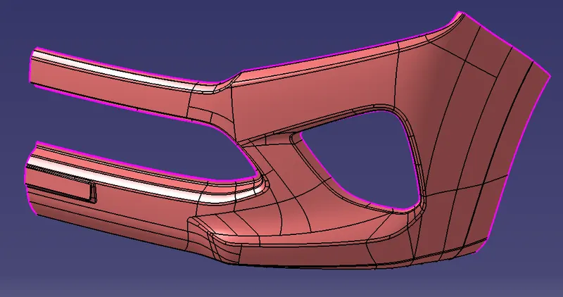
SURFACE-C Creation
Surface that joins class-A and class-B surfaces is class-C surface. Class C is often specified for interior surfaces not readily visible, surfaces that will be covered by another part when assembled
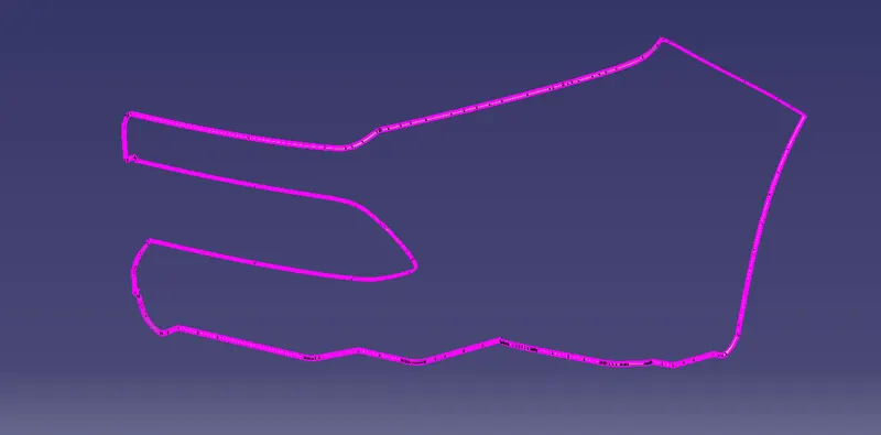
Since it is a complex class-A surface, we cannot simply create the class-A boundary curve and sweep it at one shot. Hence, we need to create smaller curves using multi-extract command and then create sweep of 90 degree with reference to the surface option. sweeps at the midportion of the bumper should have a 93 degree vaue to pass the draft analysis.
Creating the final surface of Bumper
- First step is to join the CLASS-A surface with CLASS-C surface.
- Then Trim the Joined surface with CLASS-B surface to achieve the final Bumper surface.
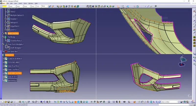
Go to the part design work bench and using the close surface command create the base bracket solid part body
Solid Body Creation-
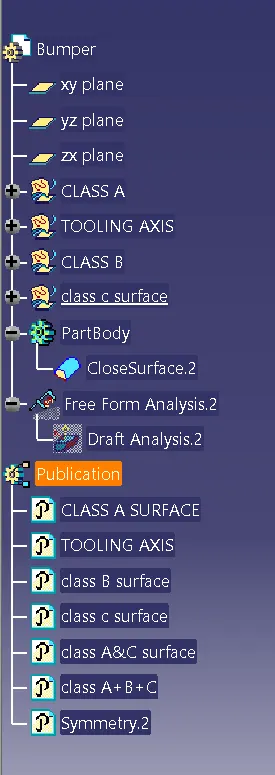
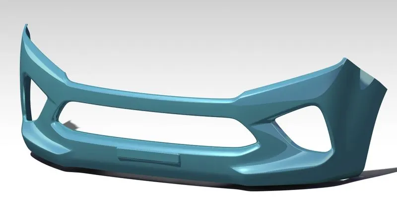
To create solid body of that closed surface, make sute there is no open edges. If there is open edges then it would not be possible to create solid body. After make sure, go to part workbench and make the closed surface part a solid body using 'Closed Surface' command. this operation must be inside a 'Body' set not inside a 'Geometrical Set'. So my final solid body look like-
3D Part model in various orientations (Isometric, Front, Side, and Top View)
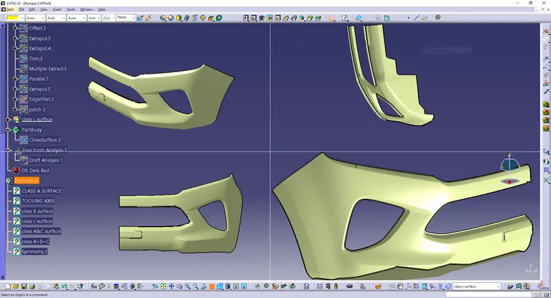
Draft Analysis-
Draft analysis is a most importent thing for a part body design. Its reasult says that the perticular body is manufacturable or not. Even it also analise that how simple or complex will be the manufacturing process. So to do that analysis first we have to create a tooling axis that will be along the movement of mould open and close axis.
Tooling axis-
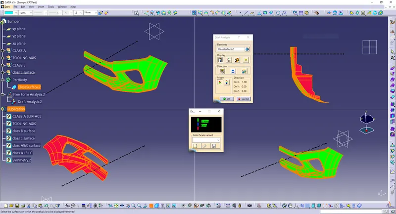 For this case as head lamp hole is concerned, so we will consider the perpendicular axis of that head lamp hole for creating the tooling axis. So we will analyse bothe perpendicular plane of that head lamp hole.

So from the picture we can say that all surfaces of solid body are clearing the minimum draft angle. From the reasult we can say trhat part is manufacturable.
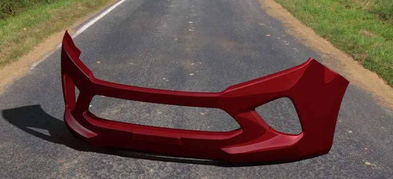
Conclusion : The Bumper is created with consedering all Design Methodology.