Week 9 - Project 1 - Door Trim Lower with Engineering Features
AIM
Create the DOOR LOWER TRIM Plastic component through the given Class-A surface. To begin with, the tooling axis for the given Class-A Surface should be created meeting the requirements of the draft angle and at the end perform the Draft analysis on the model.
Create the Heat Stakes and the locators considering the design rules mentioned in the video for the door applique.
INTRODUCTION
A DOOR LOWER TRIM is a structure attached to or integrated with the front and rear ends of a motor vehicle, to absorb impact in a minor collision, ideally minimizing repair costs and easy to access service ability
MATERIAL : polyvinyl chloride (PVC)
PVC (plasticised) is less rigid; has high impact strength; is easier to extrude or mould; has lower temperature resistance; is less resistant to chemicals, and usually has lower ultimate tensile strength. The variability from compound to compound in plasticised PVC is greater than that in PVC-U.
Door panels serve as an interface between the interior of the car and the inner workings of the door, and between vehicle occupants and the door. They are expected to meet a variety of design specifications regarding safety, aesthetics, and functionality. In addition, they are expected to continue the material theme of the dashboard and pillars while concealing intricate electrical and mechanical components for operating locks, windows, and other features. The door panel has evolved from a simple two-part system of latch and simple winding mechanism to a more sophisticated enclosure.
- Density: PVC is very dense compared to most plastics (specific gravity around 1.4)
- Economics: PVC is readily available and cheap.
- Hardness: Rigid PVC ranks well for hardness and durability.
- Strength: Rigid PVC has excellent tensile strength
|
Property |
Value |
|
Technical Name |
Polyvinyl Chloride (PVC) |
|
Chemical Formula |
(C2H3Cl)n |
|
Melt Temperature |
212 - 500 °F (100 - 260°C) *** |
|
Heat Deflection Temperature (HDT) |
92 °C (198 °F) ** |
|
Tensile Strength |
Flexible PVC: 6.9 - 25 MPa (1000 - 3625 PSI) Rigid PVC: 34 - 62 MPa (4930 - 9000 PSI) ** |
|
Specific Gravity |
1.35 - 1.45 |
OBJECTIVE
- To design DOOR LOWER TRIMas per automotive industry Standard.
- Create tooling axis for the given CLASS-A surface.
- Create B Class and C Class surfaces
- Create final surface model and convert it into solid body using close surface command in the part design workbench.
- Perform draft analysis for both Class-A surface and Final part body.
- Create the Heat Stakes and the locators considering the design rules mentioned in theas per automotive industry Standard..
Class A Surface:
- Visible surface and aesthetic look.
- Surface with textures.
- Surfaces provided by customer(OEM).
- Don't have any features like(rib, snap, bosses, etc) on class A surface.
Class A surface is made from scanned data with different software like alias
- Surfaces which are having CURVATURE CONTINUITY IS CALLED class-A.
Class B surface is
- Invisible Surfaces.
- Surface mostly don't have textures.
- Surface needs to be created according to the class-A surface.
- Having all features(Rib,boss,snap etc) in B-side surface only.
- Surfaces which is having TANGENT CONTINUITY IS CALLED class-B.
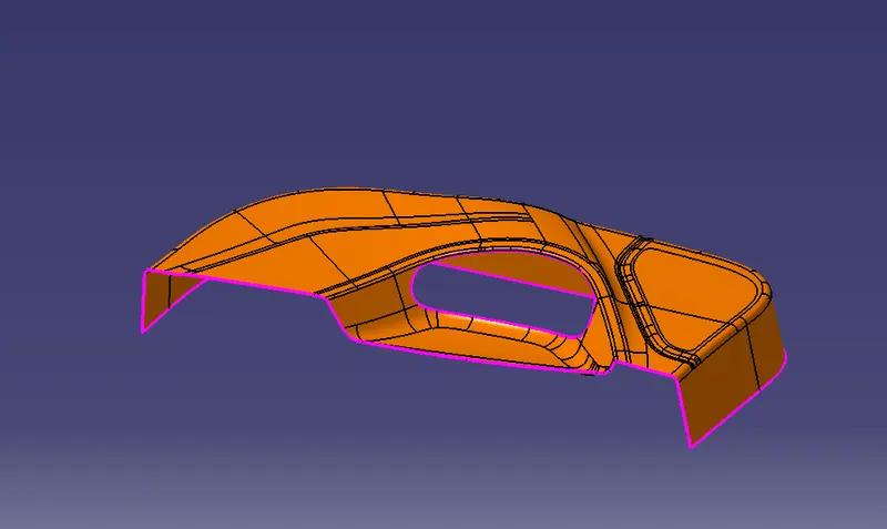
Class A Surface : Check the connectivity of the Class A Surface Ensure that there is no gap between the component, using join command. We can visually check it or by clicking boundary command. It has a boundaries outer. Therefore first check completed.
Class-A surface means visible surface. It gives the aesthetic of the component which is created by the styling team and gives to the part design engineer to create the part with all engineering aspects.
The first step is to check the continuity of the class A surface. This is to ensure that there is no gap between surfaces. If we find any then we should fix that first.
Class-A continuity check
Analyse the class A surface through visual inspection.
To make sure that the given surface has no gap in between them. We can check it also with the help of Join or boundary commands.
Procedure :
Tooling Direction for Plastic Part : Tooling direction is main consideration for plastic part and mold parts because it defines movement of mold part and possibility of plastic part to come-out from mold part (Core and Cavity).
- In Molding machine arrangement is given to open the mold along a direction which is known as Tooling Direction.
- In other words. The mold is built from two separate halves (Core and Cavity) and tooling direction basically define the direction of mold pulls apart.
- Tooling direction is known as primary direction.
Preparation of Tooling Direction
While creating the tooling direction in given class A surface. Chose the one suitable Base and Side wall and draw the line direction of axis
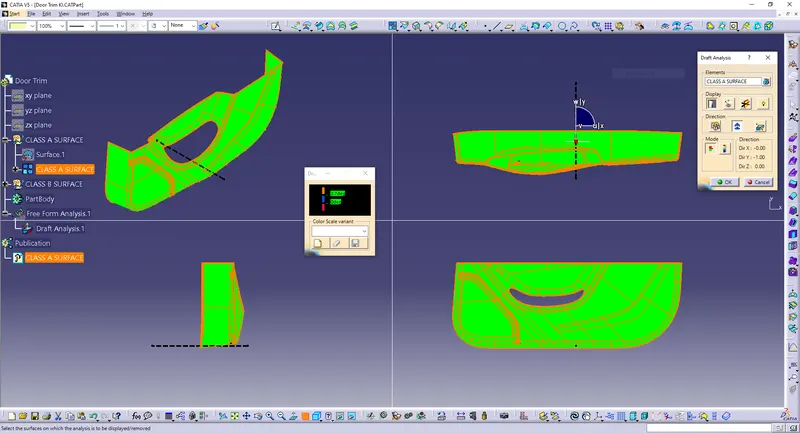
Draft analysis for the given CLASS-A surface.
Draft analysis for the given CLASS-A surface.
The Draft Analysis is a command enables you to detect if the part you drafted will be easily removed. This type of analysis is performed based on colour ranges identifying zones on the analysed element where the deviation from the draft direction at any point, corresponds to specified values.
Draft analysis is done after determining the tooling axis, draft analysis is used to check whether the minimum draft (3 degrees) is maintained or not.
- Procedure for performing the draft analysis are as follows
- Change the view mode of the component to be in customized parameter mode and then select the shading mode as materials.
- Then open the featured draft analysis tool from the insert menu.
- Then click on use the compass to define the current drafting direction and then drag and align the compass on the Tooling axis.
- Then lock the draft direction and perform draft analysis by clicking on the component.
-
- The green colour shows the positive daft tooling direction and the given surface passes the draft analysis.
- Click on the analyses under the running point to check the draft analysis on the individual faces. It shows how much draft on specific points when we move the cursor point.
SURFACE-B CREATION
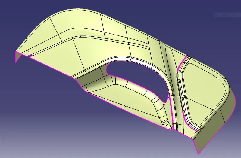
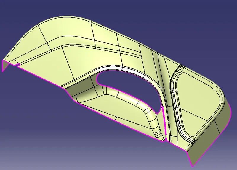
Class-B surface means thickness of a part it is not visible and is inside part. In other words, Class-B surface is a surface below a certain thickness from the class-A surface. This is the surface that contains engineering aspects of a model.
-
- Offset the class-A surface to 2.5 mm inward direction.
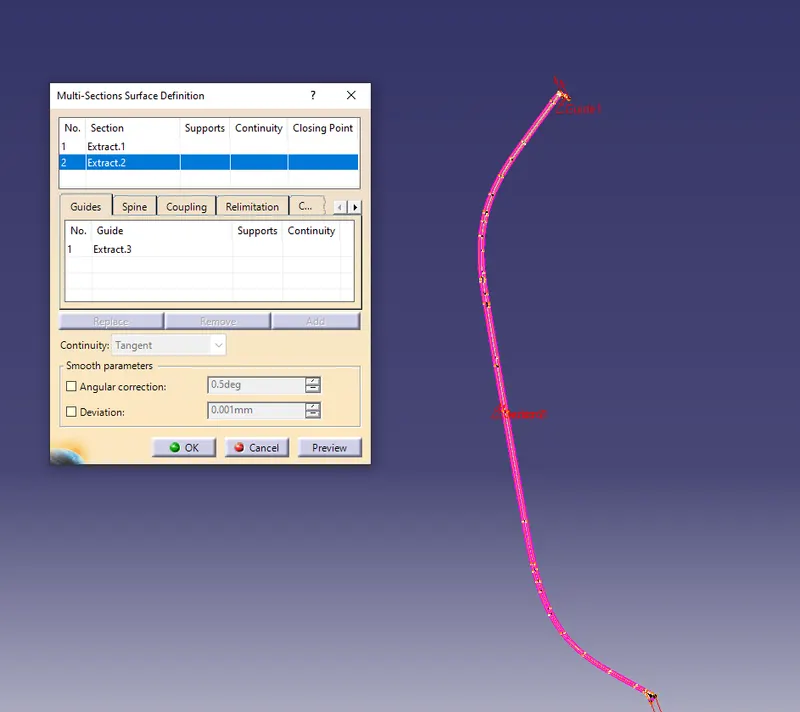
- Rework on the patches and discontinuity of the offset surfaces using the features like extract, multi-extract, sweep, multi-section surfaces, extrapolate.
- To ensure the continuity of the Class-B surfaces check the boundary command to find out the boundary.
- Hence class-B surface creation is done.
SURFACE-C Creation
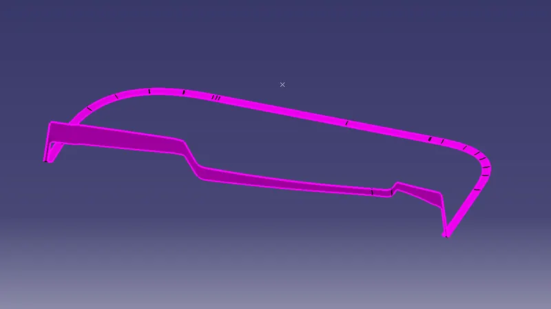
Surface that joins class-A and class-B surfaces is class-C surface. Class C is often specified for interior surfaces not readily visible, surfaces that will be covered by another part when assembled
Since it is a complex class-A surface, we cannot simply create the class-A boundary curve and sweep it at one shot. Hence, we need to create smaller curves using multi-extract command and then create sweep of 90 degree with reference to the surface option. sweeps at the midportion of the DOOR LOWER TRIM should have a 93 degree vaue to pass the draft analysis.
Creating the final surface of DOOR LOWER TRIM
- First step is to join the CLASS-A surface with CLASS-C surface.
- Then Trim the Joined surface with CLASS-B surface to achieve the final DOOR LOWER TRIM
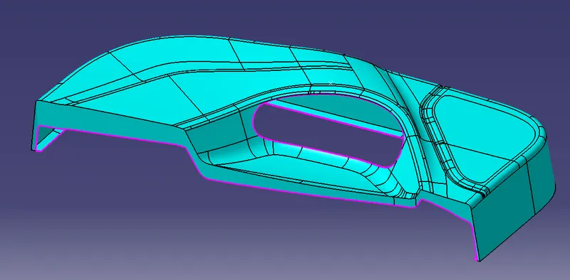
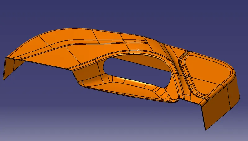
Go to the part design work bench and using the close surface command create the base bracket solid part body
Solid Body Creation-
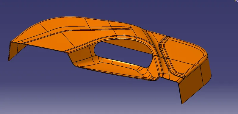
To create solid body of that closed surface, make sute there is no open edges. If there is open edges then it would not be possible to create solid body. After make sure, go to part workbench and make the closed surface part a solid body using 'Closed Surface' command. this operation must be inside a 'Body' set not inside a 'Geometrical Set'. So my final solid body look like-
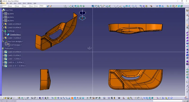
3D Part model in various orientations (Isometric, Front, Side, and Top View)
Draft Analysis-
Draft analysis is a most importent thing for a part body design. Its reasult says that the perticular body is manufacturable or not. Even it also analise that how simple or complex will be the manufacturing process. So to do that analysis first we have to create a tooling axis that will be along the movement of mould open and close axis.
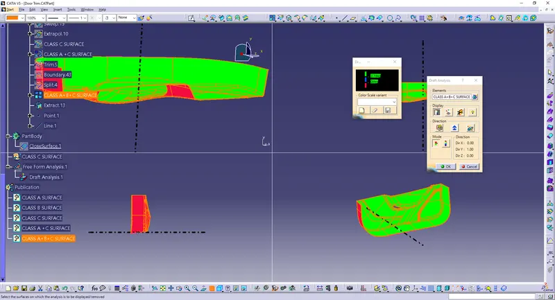
Tooling axis & DESIGN TREE
For this case as head lamp hole is concerned, so we will consider the perpendicular axis of that head lamp hole for creating the tooling axis. So we will analyse both perpendicular plane of that head lamp hole.
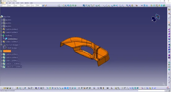
So from the picture we can say that all surfaces of solid body are clearing the minimum draft angle. From the result we can say that part is manufacturer.
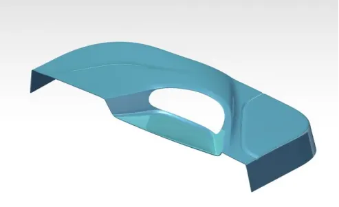
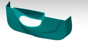
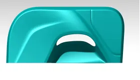
The locators restrict all the other degrees of freedom except the translation along the direction of tooling axis Le along y-axis. For restricting that degree of freedom we will be using the heat stakes.
In heat staking, we use local heating and cooling to raise the temperature of plastic components and allow plastic reforming to be carried out.
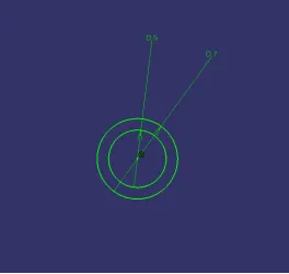
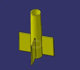
The draft is applied to the sides of the ribs. As per the design rule, the ideal draft angle is 0.5 deg The yellow colored cylinders are the heat stakes.
These heat stakes will enter the mating component and using a heat staking machine these heat stakes are melted and cooled. When cooled this will get hardened and the two components will stick together. Thus all degrees of freedom are arrested Then, the ribs are created by following the rib design rules
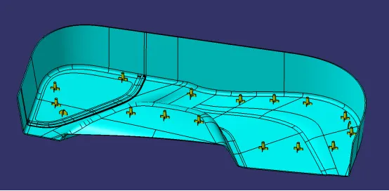
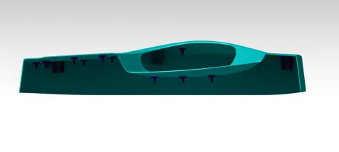
Hence, the ribs are created for the screw HEAT STAKES
Now we will see how the plastic part is fixed onto the other plastic part. The door applique is fixed on to the door surface with the help of locators and heat stakes. Every component in space has 12 degrees of freedom. So these locators and heat stakes restrict all these degrees of freedom.
Locators are 4-way locators. The locators will follow the rib design guidelines and will be given a minimum draft of 0.5 degrees and a minimum fillet of 0.2mm and an entry chamfer of 3mm. This entry chamfer is given so that the locators can mate with the other part easily.
The draft is applied to the sides of the ribs. As per the design rule, the ideal draft angle is 0.5 deg
CREATING THE DOGHOUSE
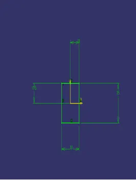
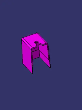
The dog house is an engineering feature used in the plastic trim design. Dog houses are used as a supporting feature. Sometimes other engineering features like snaps; locators, etc. are mounded on them to increase their strength.
The doghouse is created by following the design rules.
The nominal wall thickness guide range is from 0.75 mm to 3 mm for reinforced materials and 0.5 mm to 5 mm for unreinforced materials.
Related Courses
WALL THICKNESS (W) = 0.70 (NOMINAL THICKNESS OF PLASTIC MATERIAL)
This process is usually done by Thicken surface command.
The fillets and the draft are given as per the design rules.
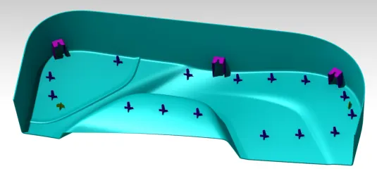
An important thing while designing a doghouse is to maintain 40% less thickness than the wall thickness (T) at the area of the intersection to avoid sink marks. So, a C shape is formed at the intersection.
This can be made using the split command to remove the solid at the intersection
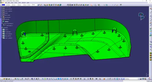
Draft Analysis
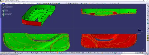
Conclusion : The DOOR LOWER TRIM is created with considering all Design Methodology.