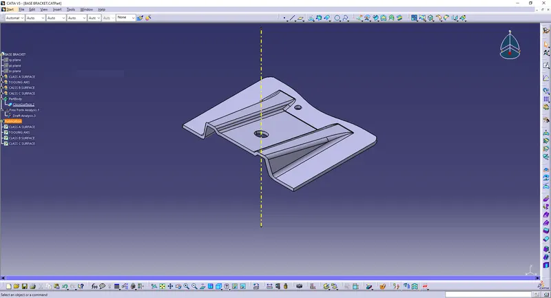
Week 8 - Challenge 1 - Base Bracket Design
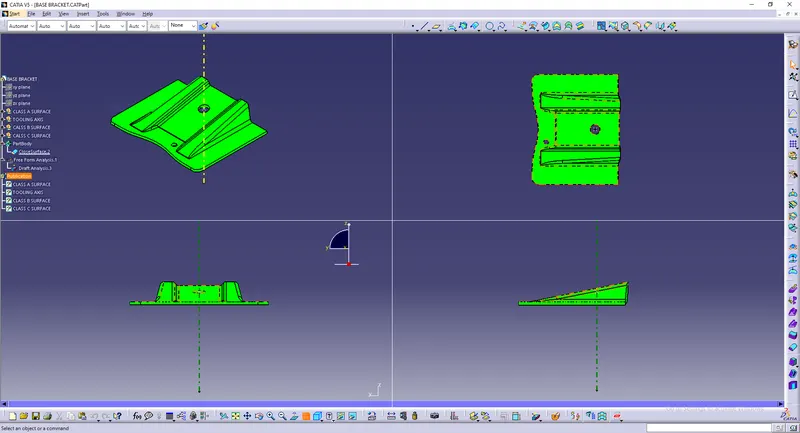
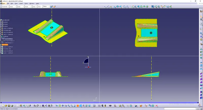
Draft Analysis
When a plastic component is made, we can observe that there is a draft angle given on each side from the base which is lesser than 90 degrees. This is because in the criteria of making a plastic material the mold should release the material when finished. if the mold surfaces are 90 degrees the material won't release from the mold because of friction due to contraction of material when cooled.
To resolve this problem we CAD engineers maintain a standard rule to design the plastic mold or die's in such a way that there is no problem while ejecting the plastic component. So a minimum of 3 - 10 degrees of draft angle is given to every plastic component while designing.
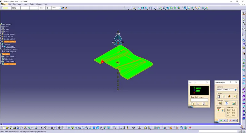
Tooling axis creation
The tooling axis is the direction of drawing a sheet metal where the finished component is easily ejected on a particular direction and axis. The tooling axis is important for removing the material when finished.
Class A Surface
Class A surface are primarily used in the automotive environment and refer to those surface which are visible in a product. In other words: A-clas surface are aesthetic/free form surfaces, which are visible to us, and have an optimal aesthetic shape and high surface quality.
The surface or the region which are visible nowadays are considered as Class-A modelling. it is one of the reason why the importance of Class-a modelling is increasing day by day. Majority of the time this term is used in Plastic part designs.
Class B Surface
The Class B finish is a quality finish with only minimal imperfections. A Class B finish is the most common finish for exterior surfaces. It is normally specified on surfaces such as external covers, panels, and parts that are fairly prominent.
Class C Surface
The Class C finish allows more imperfections than Class A or B. Class C is often specified for interior surfaces not readily visible, surfaces that will be covered by another part when assembled, or surfaces which the Customer feels do not need to meet a high cosmetic finish. This Class is generally used for parts or surfaces which are not viewed after installation or viewed only for service.
Material
Duroplast is a composite thermosetting plastic, a close relative of Formica and Bakelite. It is a resin plastic reinforced with fibers (either cotton or wool) making it a fiber-reinforced plastic similar to fiberglass.
Creation of tooling axis (bisecting method).
uses: It was also used to make suitcases. Duroplast is light and strong. It is made of recycled material, cotton waste and phenol resins. Because it can be made in a press similar to shaping steel, it is more suitable for volume car production than fiberglass.
Step 1:
Identify the required and most perfect plane which is suitable for creating a tooling axis.
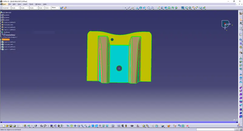
the XY plane is most suitable for the creation of the tooling axis.
Step 2:
Create a dummy axis that will be used until creating an original tooling axis. And then take reference curve by taking a section from the ZX plane and using those boundary curves for creating a bisecting curve and that curve will be the tooling clearing for x-direction.
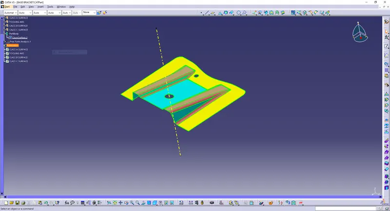
dummy tooling axis
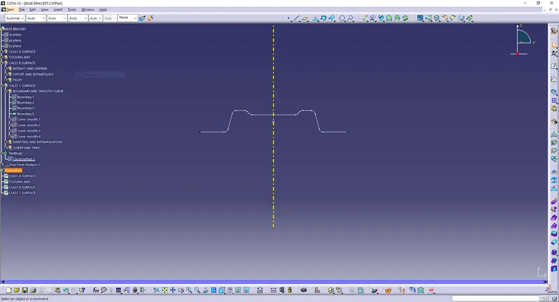
tooling axis using the bisecting method
Step 3:
after creating the actual axis curve we can now perform the draft analysis on the given class-A surface. before performing the analysis change material property to customizable view parameters.
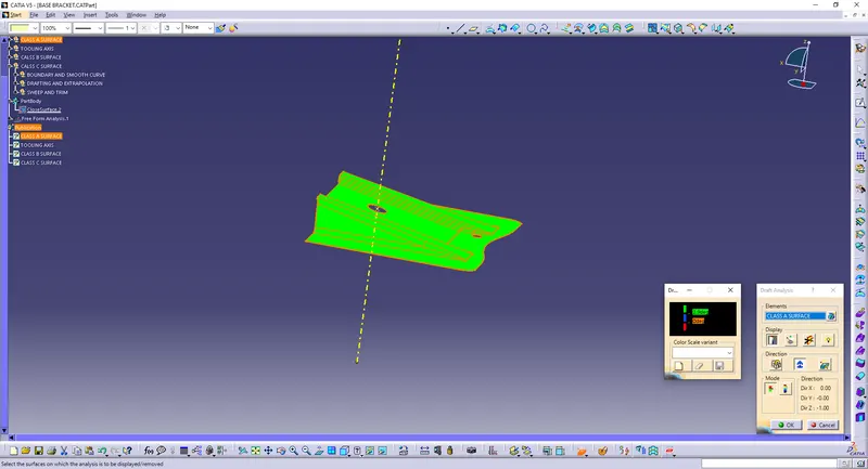
Step 4:
After the Draft analyzing if the Class A surface is 'ok,' we can create the class B surface which will be about 2.5 mm thickness.
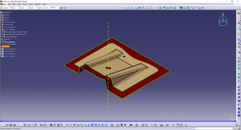
designing of RIB 1 and 2.
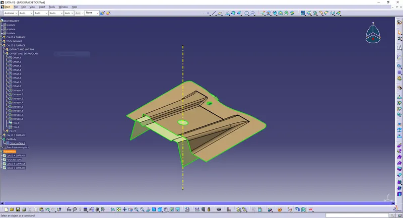
complete creation of B surface
Step 5:
After completing the class B surface. the next step is to create the Class C surface. This surface will join the Class A and B surfaces together using the boundary of the Class A surface.
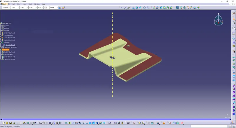
before trim and join of all surfaces with Class A surface.
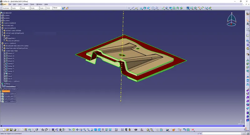
After joining all surfaces with class A surface.
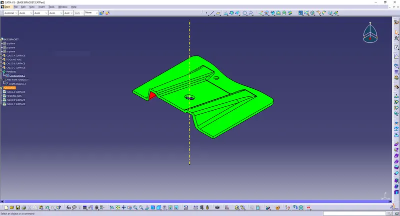
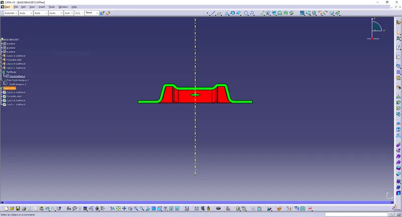
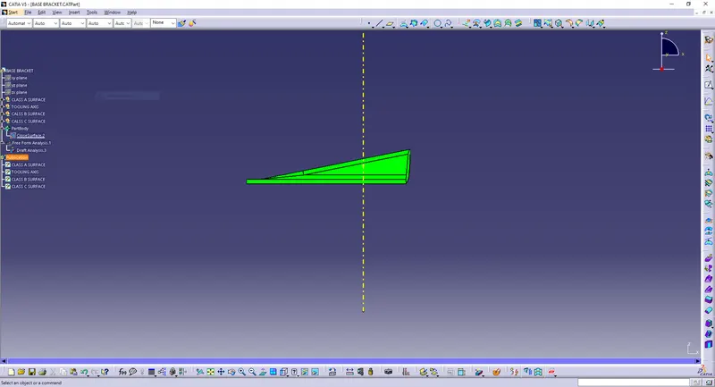
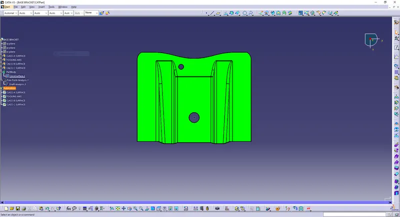
Various views of solid model