Week 4 Challenge
AIM:
- Define tooling direction
- Create tooling direction for Class A with 10 deg draft ( draft in command should be 10 deg) and show the draft analysis
- Write the definition of the Parting line
- Create B surface of the given lens in surface modeling (not in part), with a 4 mm thickness
- Create a Parting Line for thickened lens and create a report for how you approached the parting Line and did a draft analysis?
The operation to do:
- Joining of Class A surface.
- Create Tooling Axis.
- Create Draft Analysis for Class A Surface.
- Create Class B Surface.
- Create Class C Surface.
- Create Final Product.
The material used in Lens:
- Poly Carbonate.
Followed Constraints:
- The change in dimension of the Class A Surafce is not allowed.
- Change in thickness is not allowed.
Parting Line:
- The parting line of a die-cast component represents where the two different sides of the mold come together. This line often (but not always) marks the border between the inside and outside of the part
Tooling Axis:
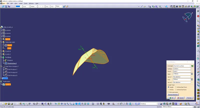
- The tooling axis for this component will be created from normal to surface. This should be done using the method of extracting the plane surface and Creating a point in the plane using a point on the surface. And finally, the line should create using the normal surface.
- It can be done using the bisecting method also.
Class A Surface:
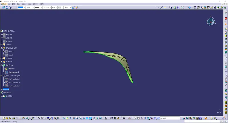
- Class A Surface is a scanned model, or the already drawn model is given for further process. It describes the final production surface data for the aesthetic parts of the car. Class A' is often misunderstood, but it's generally seen as the 'Holy Grail' of surface modeling. This is the outer layer of the model.
Draft Analysis:
- The draft analysis technique is used to analyze whether our part model created in CAD is manufacturable based on the draft condition applied. Here the part should get easily removed from the panel dies (in case of Sheet metal part) or Mold (in case of plastic). The analysis shows whether the angle given in the surface is up to the level or not. This can be identified by using Green, Blue, and Colour. Green means to perfect (< 10 deg), Blue (0 deg), and Red (> 10 deg).
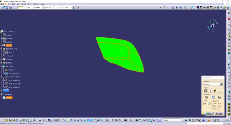
DRAFT ANALYSIS OF CLASS A SURFACE
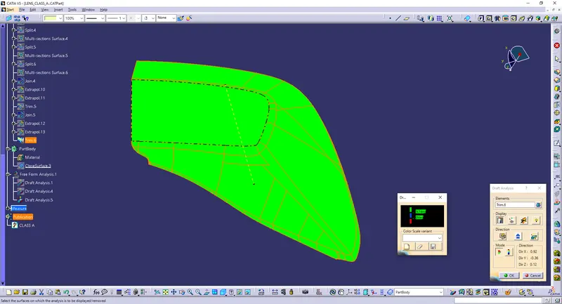
DRAFT ANALYSIS OF OVERALL SURFACE
Class B Surface:
- This is the surface followed by Class A Surface. It is the inner surface of the model with a 4mm thickness. The fillet and offset of the Surface should be given according to the Class A model. The flash from the molding process should not come into the surface of Class A, so the Class B design should not disturb the class A Surface.
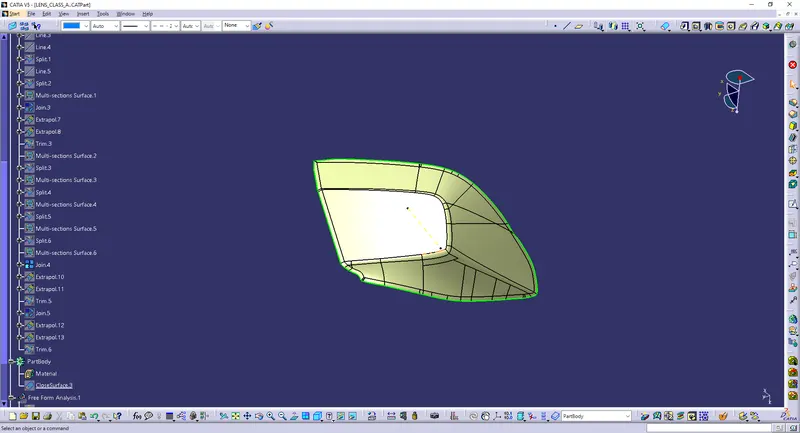
Class C Surface:
- Class C Surface is the surface that joins both class A & B using the boundary, trim, join method. The Class C finish allows more imperfections than Class A or B. Class C is often specified for interior surfaces not readily visible, surfaces that will be covered by another part when assembled, or surfaces that the Customer feels do not need to meet a high cosmetic.
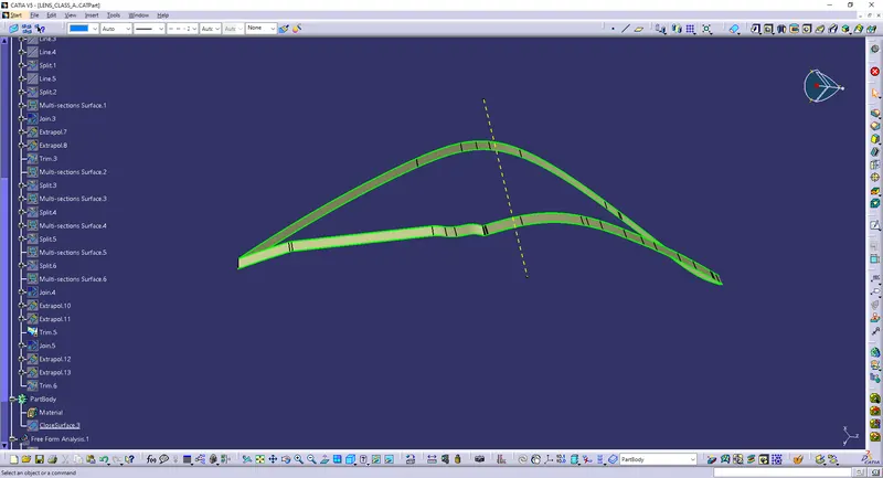
Final Product:
- The final product includes the finished surface of Class A, Class B, and Class C. Having the complete surface model of the Lens.
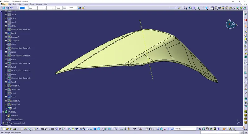
FINAL TRIM
Solid Surface:
- After the completion of the final trim, it should be changed to the Close surface.
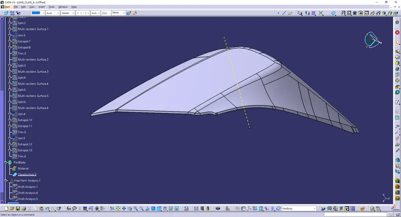
FINAL OUTPUT
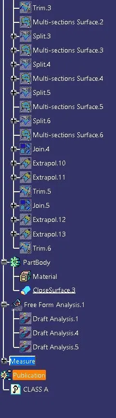
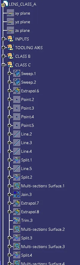
TREE STRUCTURE