Week 7 State of charge estimation
AIM: To simulate the Battery Management System (BMS) with 3 different cases in Simulink.
KEYWORDS: State flow, Kalman filter, Coulomb counting, Balancing, Fault cell, etc.,
SOFTWARE: Matlab & Simulink
OBJECTIVE:
1. Initially the model is simulated for 20000 secs with the first case and study the results based on the Kalman filter (EKF & UKF) and Coulomb counting algorithm for the estimation of SOC.
2. Simulate the model for second case and study the results.
3. Repeat the procedure for all test cases and study the results.
INTRODUCTION:
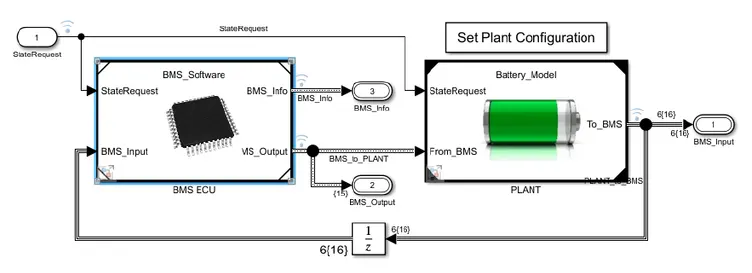
Lithium-ion batteries that possess high charge density, power most electric cars. These battery packs even though are not very big; can be highly unstable. Therefore, these batteries should never be overcharged or be allowed to reach a state of deep discharge at any point. Thermal Runaway is a condition where the current flowing through the battery on charging or overcharging causes the cell temperature to rise. Conditions like these can harm the lifespan or the capacity of the battery. To ensure this does not happen, we require BMS to monitor its voltage and current.
This process is very challenging as many cells are put together to form a battery pack in an electric vehicle and every cell needs to be individually monitored for its safety and efficient operation, which requires a specially dedicated system called the Battery Management System (BMS).
TEST CASES:
Case I:
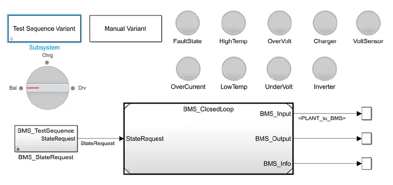
In the test sequence variant it includes 3 test cases with different step time. By clicking that and selecting the cases sequentially order wise and simulating the model for 20000 secs. The output may vary for different cases depends on the algorithm.
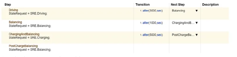
In the first test case, the steps are shown below which includes driving at initial 3000 secs and after that Balancing of cells carried out for 1000 secs and for next 5000 secs charging and balancing will happen parallely. Finally post charge balancing will occur.
Case II:
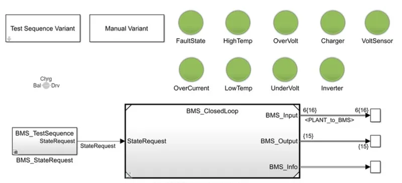
The above figure shows that, the simulation is carried out for 20000 secs without any fault or error. Here, the battery is in normal condition which is indicated in green signals.
By Switching to second test case, the steps are taken out as shown below, which includes driving for next 10000 secs and then charging occurs.

Case III:
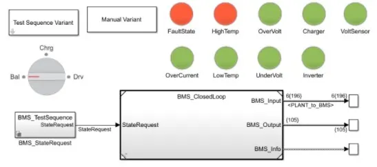
The above figure shows that, the simulation is carried out for 20000 secs with fault. Here, one of the battery cell is get affected by high temperature with bad state which is indicated in red signals.
By Switching to third test case, the steps are taken out as shown below, which includes only charging.

COULOMB COUNTING:
The SOC is one of the most important parameters for batteries. In general, the SOC of a battery is defined as the ratio of its current capacity (C(t)) to the nominal capacity (Cn). The nominal capacity is given by the manufacturer and represents the maximum amount of charge that can be stored in the battery. The SOC can be defined as follows:
SOC (t) = [ C(t) / Cn ]
The various mathematical methods of estimation are classified according to methodology. The classification of these SOC
estimation methods is divided into the following four categories.
(i) Direct measurement: In this method uses physical battery properties, such as the voltage and impedance of the battery.
(ii) Adaptive systems: In the adaptive systems are self-designing and can automatically adjust the SOC for different discharging conditions. Various new adaptive systems for SOC estimation have been developed.
(iii) Hybrid methods: In the hybrid models benefit from the advantages of each SOC estimation method and allow a globally optimal estimation performance. The literature shows that the hybrid methods generally produce good estimation of SOC, compared to individual methods.
(iv) Book-keeping estimation: Book-keeping estimation method uses battery discharging current data as input. This method permits to include some internal battery effects as self-discharge, capacity-loss, and discharging efficiency. Two kinds of book-keeping estimation methods have been employed: Coulomb counting method and modified Coulomb counting method.
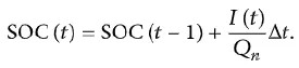
1) Coulomb counting method: The Coulomb counting method measures the discharging current of a battery and integrates the discharging current over time in order to estimate SOC . Coulomb counting method is done to estimate the SOC(t) , which is estimated from the discharging current, I(t), and previously estimated SOC values, SOC(t). SOC is calculated by the following equation:
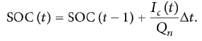
2) Modified Coulomb counting method: To improve the Coulomb counting method, a new technique called modified Coulomb counting method is proposed. The modified Coulomb counting method uses the corrected current to improve the accuracy of estimation. The corrected current is the function of discharging current. There is a quadratic relationship between the corrected current and discharging current of battery. By practice of experimental data, corrected current is calculated by the following form:
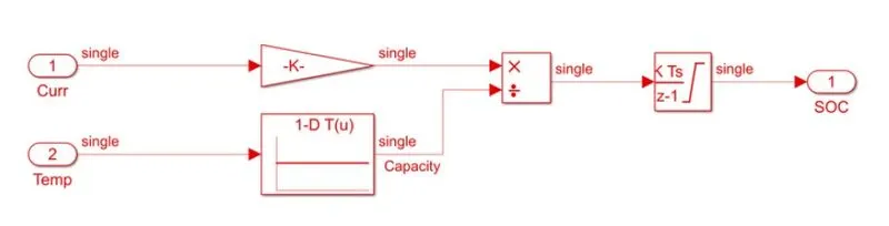
where as,

RESULTS:
Case I:
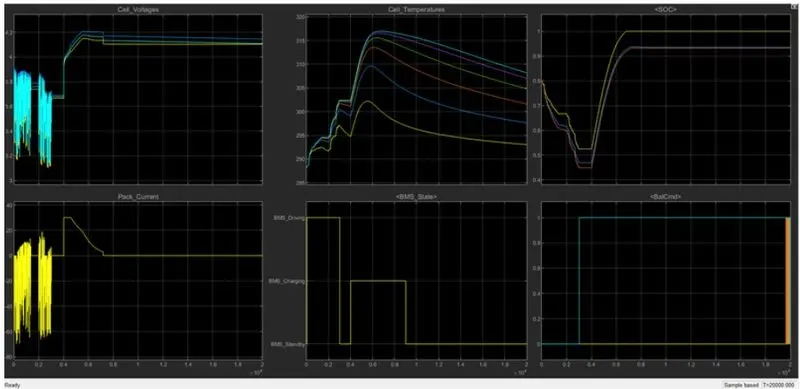
In the above figure, the cell voltage and current is fluctuating for first 3000 secs (Driving state) as per the step. The next 1000 secs, the cells are in balancing state in which it maintains a constant voltage and current and after that it starts chraging the cell where the cell voltage get increased parallely current also increasing.
The cell temperature for all the 6 cells are varing based on usage of current and voltage, where as the first cell is insulated (less temperature) and the last cell is not insulated (high temperature).
In the estimation of SOC, the yellow line shows the Coulomb counting algorithm and other two lines are Kalman filter (EKF & UKF) algorithm respectively.
Case II:
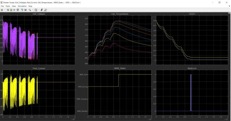
In the above figure, the cell voltage and current is fluctuating for first 10000 secs (Driving state) as per the step. The next 10000 secs, the cells are in charging state in which it maintains a constant voltage and current.
The cell temperature for all the 6 cells are varing based on usage of current and voltage, where as the first cell is insulated (less temperature) and the last cell is not insulated (high temperature).
In the estimation of SOC, the yellow line shows the Coulomb counting algorithm and other two lines are Kalman filter (EKF & UKF) algorithm respectively.
Case III:
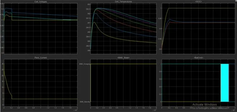
In the above figure, from 0-20000 secs, the cells are in charging state in which it maintains a constant voltage and current.
The cell temperature for all the 6 cells are varing based on usage of current and voltage, where as the first cell is insulated (less temperature) and the last cell is not insulated (high temperature).
In the estimation of SOC, the yellow line shows the Coulomb counting algorithm and other two lines are Kalman filter (EKF & UKF) algorithm respectively.
CONCLUSION:
The main function of BMS is to ensure that the battery is protected and any operation out of its safety limit is prevented. It monitors the battery pack’s state of charge (SOC) along with the state of health. BMS also manages the battery optimization via cell balancing that improves the life of the battery in the long run. The BMS will also monitor voltage, different temperature parameters, and coolant flow.