Week 7 State of charge estimation
1.Simulate the 3 test cases from harness dashboard and write a detailed report on the results
BAttery Management System is an embedded system made up of combination of harware & software. It is used to control the electronics in battery pach using electrical and didgital signals.
Uses of BMS:
*Safe operation of battery pack
*State monitoring*Secondary data calculation
* Report generation
*Aurhenticate, balance & control environment
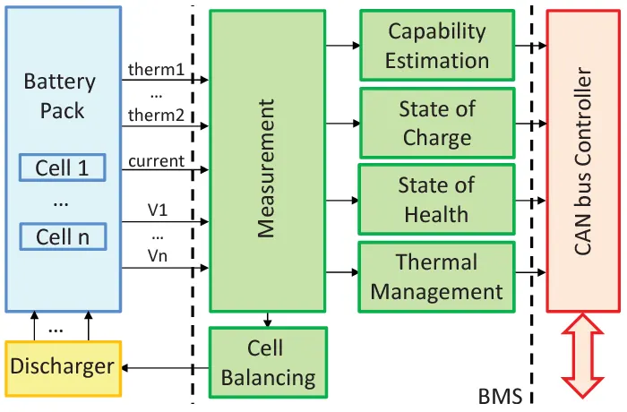
>>BMS flow chart
>>The file “Battery management System” is downloaded from the given file and extracted.
>> “ Battery_System_R2020a>>Tests>>System>>BMS_ClosedLoop-Harness_Dashboard” MATLAB file is opened.
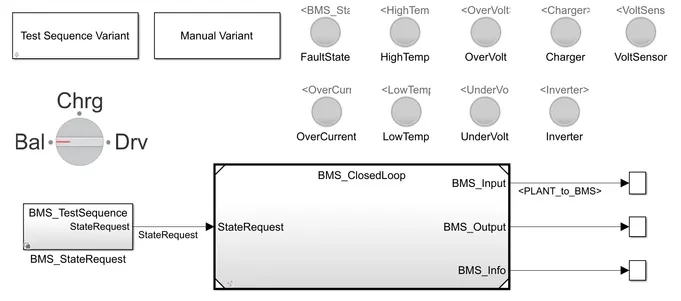
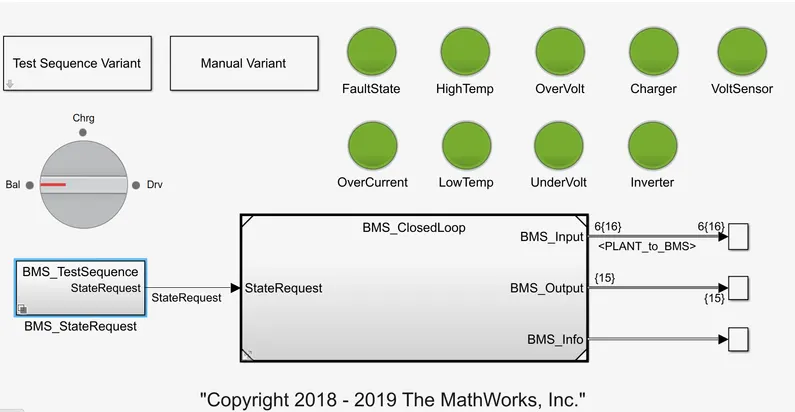
>>The above system has a set of lights thats shows the state of 'Fault state, high temperature, over voltgae, charger, voltSEnsor, over current, Low temperature, Under voltage & Inverter'
>>Green light shows the working & red light shows the fault.
>>The BMS_ClosedLoop ha the following sysytems in it to govern the flow process of the battery
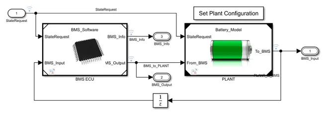
>>The BMS Elecrical Control Unit(ECU) with its various monitoring & control algorithm is connected to a battery pack associated circuitry & peripherals.
>>It contains 2 battery packs one with 6 series connected cells & other with 16 large module pack, each containing 6 series connected strings.
>>Test harness is opened from “Test sequence variant” block.
>>“Test sequence variant” is opened and test number is selected (1,2,3).
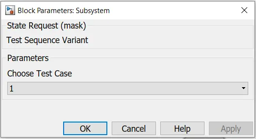
>>The selected test number is mentioned in the “BMS_StateRequest”
>>Each Test sequence variant is selected and run for 20000 seconds as shown below:
TEST CASE 1:
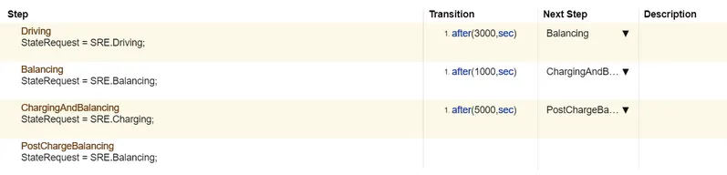
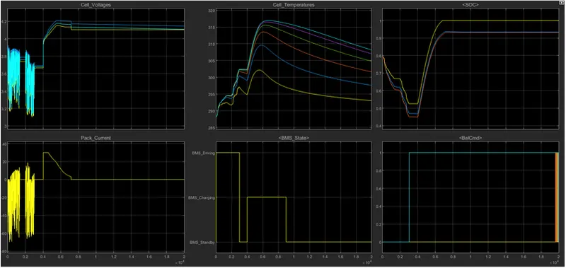
*In this case, the vehicle is in driving mode for 3000 s followed by balancing mode till 4000th second, charged for next 5000 seconds and goes to balancing mode.
*Initially the vehicle is in the driving state and charged till 90%.
*From BMS plot, we can see that after charging it reaches standby mode.
*The battery temperature increases while charging & driving. It increases to maximum of 4.2V while driving.
*The SOC reduces below 50% while driving & increases when charged.
TEST CASE 2:
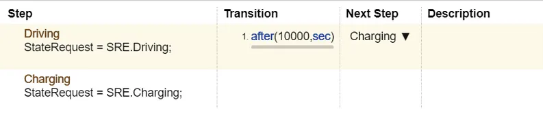
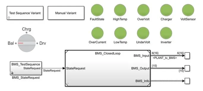
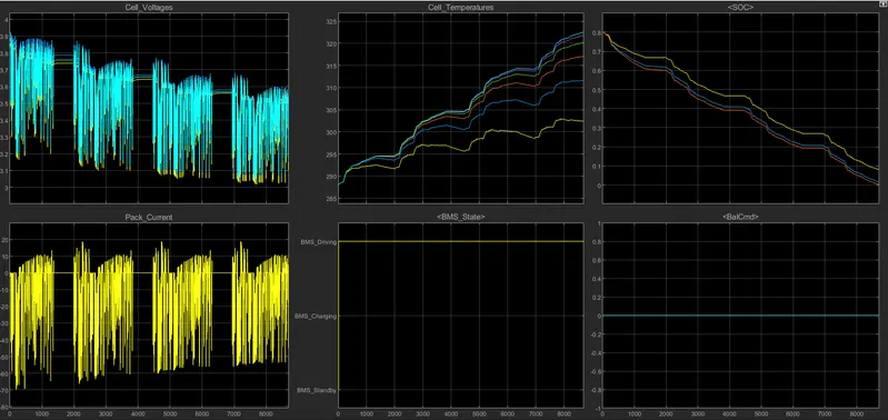
*In this case, the vehicle is in driving mode for first 10000 & goes to charging for the remaining time.
*From the graphs we can observe that the battery discharges completely at 8692th second and stops mid- way.
TEST CASE 3:

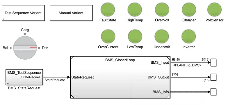
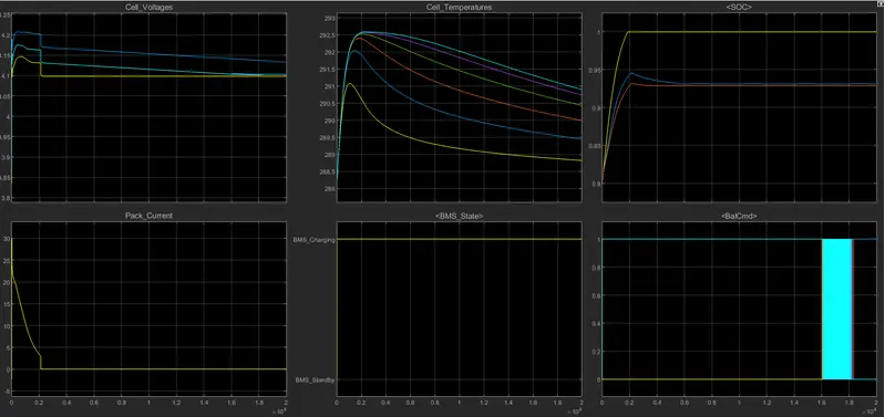
*In this case, the vehicle is in charging mode for entire 20000s.
*The battery gets charged in 2000s & the SOC remains constant 100% for the rest of the simulation time.
2.What is coulomb counting? Refer to the above model and explain how BMS implements coulomb counting for SOC estimation ?
COULOMB COUNTING:
Coulomb counting is used to estimate SOC integrating the measured discharge current over a period of time.
SOC(t)=SOC(t-1) +( I(t)/Qn * Δ t)
Here,
SOC - State Of Charge
I(t) – discharge current
Qn – Nominal battery capacity
>> Coulomb counting is the simplest method used in baseline comparison.
*Limitations:
>>Gives inaccurate current value which results in large error, this makes current measurement expensive with other methods.
>>Practically the decreasing SOC of resting battery & variation with temperature change.
*Implementing BMS in Coulomb counting:
“BMS_ClosedLoop>>BMS ECU>>SOC Estimation>>Coulomb counting”
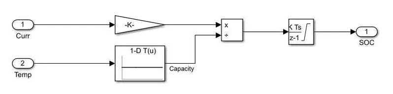
>>The coulomb counting takes the discharged current & temperature as inputs
>>The current & temperature are given to a gain block & lookup table respectively.
>>The output from gain block is divided by the output from lookup table and integrated using a ‘discrete –time integrator’ to get the SOC at that given time.