Week-7 Challenge: DC Motor Control
Q1.Explain a MATLAB demo model named ‘Speed control of a DC motor using BJT H-bridge’.
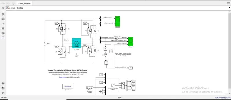
>> The 4-quadrant chopper model is loaded in the simulink.
>>In this model a DC machine is connected as load between the 4chopper switches and the closed loop torque control is implemented.
>>The H-bridge consists of 4 BJTs simulated by IGBT.
>>D1, D2, D3 & D4 are the 4 diodes across the chopper switches CH1, CH2, CH3 & CH4.
>>The pulse generator gives the pulse input.
>>The load is given an armature voltage of 240V & the field voltage of 300V DC.
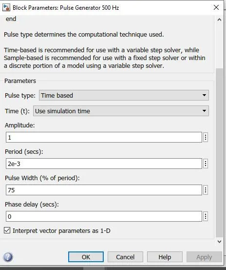
>>The duty cycle is default at 75%
>>The final output is converted from rad/sec to RPM
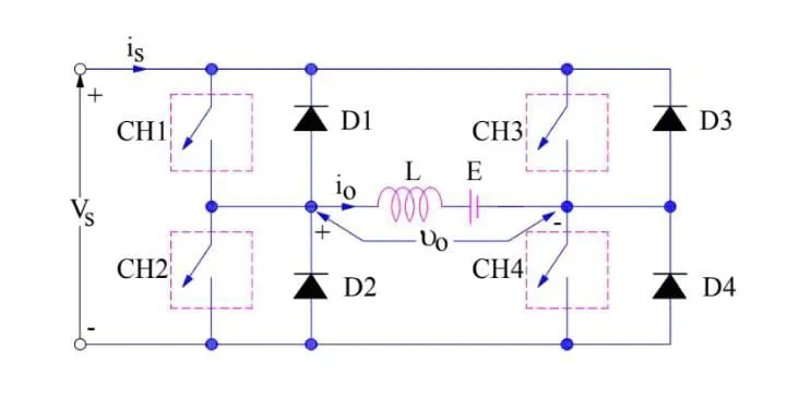
>> Quadrant 1:
*When CH1 & CH4 are ON, the load gets connected and the output voltage equals to source voltage and current flows from CH1-CH4.
*When CH1 is Off and CH4 is ON, the load current freewheels through CH4 & D2 kepping the source voltage and load voltage positive
* It is step down chopper
>>Quadrant II
*Then, When CH2 alone is ON, the DC source voltage in the load drives the current through the D4, CH2 and the current is stored in L.
*At CH2 Off, the current is fed back from D4 to D1.
*Here the load voltage is more than the source voltage. Since the current is fed back, the load current is negative.
*It is a step up chopper.
>>Quadrant III
*Here CH2 & CH3 are On.
*The load voltage & load current are positive if current flows from CH2 to CH3.
*The load voltage & load current are negative if current flows from CH3 to CH2
*When ch3 is off, the negative load current freewheels through CH2 & D4 making the load current & load voltage negative
>>Quadrant IV
*CH4 is alone turned on, the current flows through CH4, D2, L &E.
*Where the polarity of E revered and L stores the energy.
*When CH4 is off, the source is fed through D2 & D3.
*It’s a step-up chopper.
>>The model with above working is run.
>>From the output we can observe the following:
*When voltage supply is given, IGBT- 1&4 are activated, the steady state current is reached in 0.5 sec after a few milliseconds of transient state. Load & Torque curves are also similar.
*When IGBT- 2&3 are activated, it takes a comparatively longer time to reach the steady state from the transient state and the armature currents starts flowing from positive to negative direction.
*The Load & Torque curves are also decreases gradually in the transient state
*Here the maximum speed of 950RPM is achieved at a load of 6 Nm.
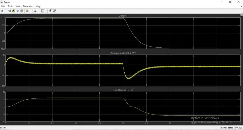
b.Comment on the armature current shoot-up from the scope results.
>>The armature current can be varied by either changing the resistance or pulse width as it doesn’t shoot up when the motor direction is changed.
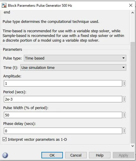
>>As the change in resistance could cause more heat dissipation losses, the duty cycle value is changed from default 75 to 50 to overcome the current shoot and run.
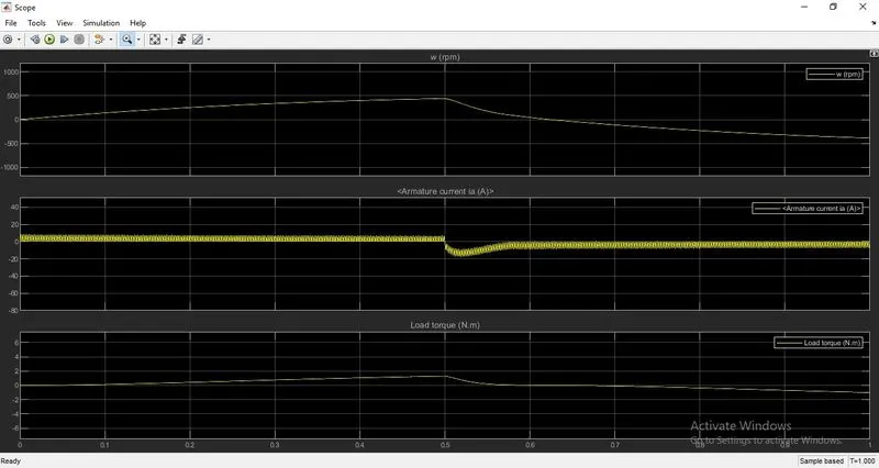
>>The following results are observed:
*No current loss
*The transient state has reduced
*The steady state is achieved in less time
*Motor achieved maximum speed in 443RPM at 1.31 Nm load.
C.Refer to the help section of ‘The Four-Quadrant Chopper DC Drive (DC7) block’. Compare it with the H-bridge model.
|
DC7 BLOCK |
H-BRIDGE MODEL |
|
It’s a 4-quadrant chopper operating in 4 modes |
It’s a 2-quadrant chopper operating in 2 modes |
|
Forward motoring, forward braking, reverse braking & reverse motoring are the 4 modes of operation. |
Forward & reverse are the 2 modes of operation. |
|
Regenerative braking is possible |
Regenerative braking is impossible |
|
Higher efficiency |
Comparatively less efficiency |
|
Speed & Current controllers are used for error detection |
Speed & Current controllers are absent making the error detection difficult. |
Q2. Develop a 2-quadrant chopper using simulink & explain the working of the same with the relevant results. (Refer to article - Multiquadrant operation of motor )
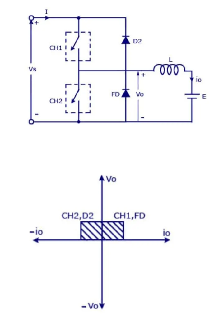
>>A two quadrant chopper is C-type chopper.
>>This quadrant is formed by connecting chopper 1 & chopper 2 in parallel.
>> The freewheeling diode is connected across CH1 & D2 across CH2.
>>A load is connected to this parallel chopper circuit.
>>Vs is the voltage supply and Vo is the load voltage.
>>This C-type chopper is has only 2 modes of operation, they are:
*Forward mode
*Reverse mode
>>General working of C-type chopper:
*When CH1 is ON, the current from the source flows to the load and the inductor stores the energy.
*Then when CH1 is off, the freewheeling diode starts conducting and the voltage source becomes equal to the load voltage making the current negative.
*When CH2 is ON, the cycle is completed via the D2.
>> C-type chopper in Simulink:
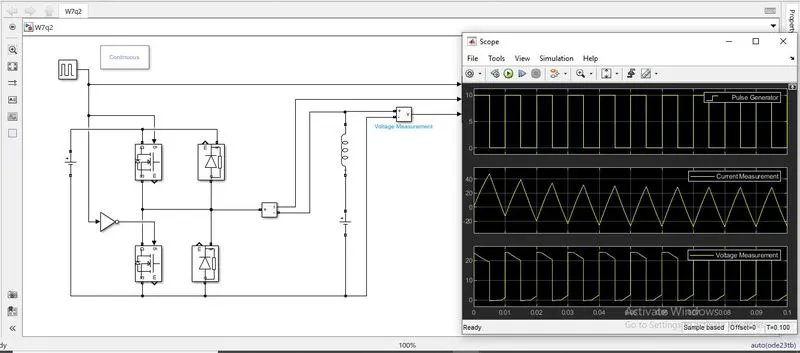
*Taking 2 blocks and 2 diode blocks and are connected as shown in the below picture.
*A 24V dc voltage source, an inductive load (L), a 12 V DC voltage source (E) and a voltage measurement block are connected.
*The input is given by a pulse generator via a NOT block to make sure that both the chopper blocks doesn’t get opened or closed at the same time.
*An amplitude of 10, period of 0.01 sec & pulse width of 50% are given to the pulse generator.
>>The simulation is run for 10 sec and the output is monitored via a scope.
>>Scope:
*The input pulse with amplitude 10 is displayed.
*The voltage wave is a positive wave.
*As per the working of chopper the current wave varies between positive & negative scale.
Q3 Explain in a brief about operation of BLDC motor
>>A brushless DC motor is a permanent magnet synchronous electric motor.
>>There are wide varities of of BLDC motors available ranging from small power to fractional horsepower, integral horse power and large power.
>>BLDC Motors are configured as single phase BLDC motors, two-phase BLDC motors, three-phase BLDC motors
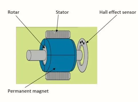
CONSTRUCTION:
STATOR: Stator of a BLDC motor is made up stacked steel lamination, wound by current carrying coils.The winding can be start connected or delta connected.
ROTOR: A permanent magnet with high flux density is used as rotor to achieve maximum torque. The number of pole pair can vary between 2 and 8 based on the requirement.
HALL SENSOR: Hall effect sensor is a sensor embedded in the stator to sense the rotor position and synchronize stator armature excitation with rotor position.
>>PRINCIPLE:
*Lorenz force law – when a current carrying conductor placed in a magnetic field, the magnet experiences an equal & opposite force.
>>WORKING:
*In the BLDC motor, the current carrying conductor is stationary while the permanent magnet rotates.
*The stator coil becomes permanent magnet and produces uniform magnetic field when the electrical supply is given to it.
*The force of interaction between the Stator and rotor makes he rotor rotate producing a mechanical output.
>>ADVANTAGES:
*High efficiency due to permanent magnet rotor.
*High operation speed in both loaded and unloaded condition due to absence of brushes.
*No commutator and related problem.
*Light weight, long life & less maintenance.
>>DISADVANTAGES:
*Permanent magnet and electronic circuits makes it costly.
*Requires complex drive circuits and additional sensors.
>>APPLICATION:
*Electrical & hybrid vehicles
*Washing machine, dryer, blowers & compressor