Week -2
1.Make a Simulink model of Doorbell using solenoid block with the following details:
In the above arrangement, when the switch is closed the electromagnet receives electrical power from the battery and pulls the metal arm to hit the bell producing sound.
Create a situation where the switch is closed for 2 seconds and then released. Observe the physical movement of the plunger.
Assume remaining parameters.
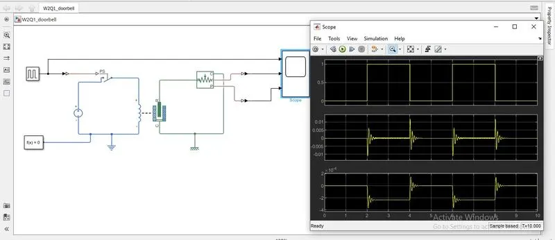
>The model of doorbell using a solenoid is model as follows:
>A solenoid block is taken from the simscape.
>A pulse generator is taken to give input pulse to the model at required intervals. A phase delay of 2 seconds is set to create the situation where the switch closes for 2seconds and then released.
>Output of pulse generator is given to scope.
>The output from the pulse generator is given to an electrical switch via a Simulation-PS converter.
>The switch is connected to positive of voltage source at one end and to the positive of the inductor in the solenoid block.
>The negative of the voltage source is connected to the negative of the inductor in the solenoid block, thus the electrical side of the circuit is closed.
>Further a solver configuration and an electrical reference is connected to the electrical side of the system.
>R & C of the solenoid is connected to the R & C of the ideal translational motion sensor.
>V & P are connected to the scope which give the velocity and position of the solenoid with respect to R & C, via PS-Simulation block.
>The system is run and the output is attached below.
2. Use a thermistor to sense the temperature of a heater & turn on or turn off the fan as per the below conditions:
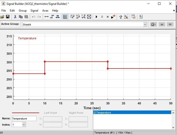
Temperature source: 20 °C from 0 to 10 seconds, 27 °C from 10 to 30 seconds, 23 °C from 30 to 50 seconds
Fan conditions: ON if the temperature above 25 °C, OFF otherwise
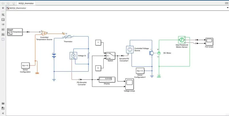
>The input temperature in Kelvin with respect to time is given to the signal builder, which is connected to a controlled temperature source via a simulation-PS block.
>In the controlled temperature source the A port is given to a solver configuration and the B port to the thermistor.
>A thermal reference and solver configuration is connected to the thermal side of circuit.
>Positive of a thermistor is given to battery positive and negative to the resistor positive. Thus the batter negative and the resistor negative close the circuit.
>Further an electrical reference is connected o he loop and the voltage is measured across the resistor via a voltage sensor.
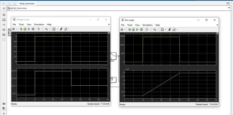
>Voltage from the voltage sensor is monitored using a scope and a display. It is also given to a switch to detect the threshold voltage and switch on the fan when temperature goes above 25 deg.C (298.15 K) with respect o its voltage.
>When the voltage is greater than the set threshold voltage, the switch, switches to constant 1 and send a signal to ON the fan else to 0 and no action is further taken.
>The controlled voltage source receives the signal and the DC motor is turned ON.
>Thus the R & C of DC motor connected to the R & C of the ideal rotational motion sensor, senses the velocity and position of the motor and displays via the scope.
>A solver configuration and mechanical reference are given to the electrical and mechanical sides if the DC motor respectively.
>Thus the model is run for 50second and the results are attached below.