Project 1- Traffic Jam Assistant Feature
AIM:
To perform the following:
- This model must be developed in MATLAB Simulink as per MBD guidelines.
- Code Generation Profile must be in Embedded Coder.
- Simulink Data Dictionary must be created for the model & must be linked to the model.
- Model Advisor Report is mandatory & this will be followed by Code Generation
Procedure:
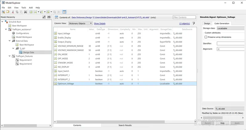
A data dictionary is created with the given input values of constants & signals.
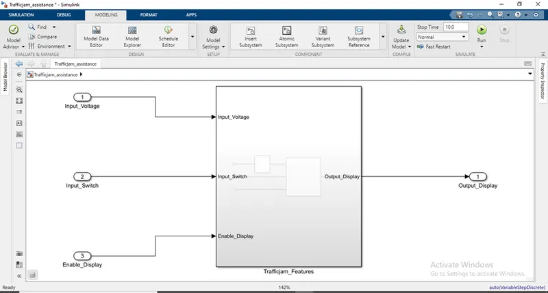
The main subsystem “Trafficjam_Features” is created with the inputs ‘Input_Voltage, Input_Switch, Enable _Display’ and output ‘Output_Display’.
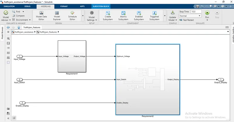
Inside the main subsystem “Trafficjam_Features” 2 subsystems “Requirement1 & Requirement2” are created.
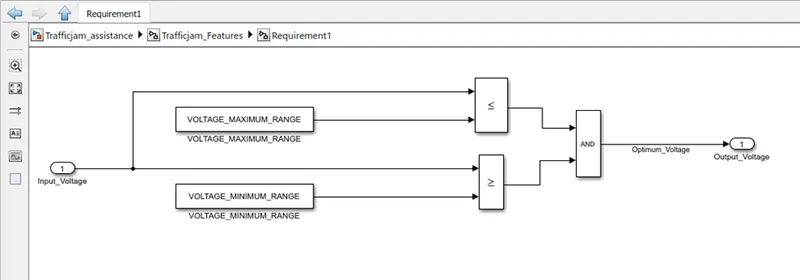
“Requirement1” takes ‘Input_Voltage’ as input and compares with the constants ‘VOLAGE_MAXIMUM_RANGE’ & ‘VOLAGE_MINIMUM_RANGE’.
Outputs from both the comparators are logically operated with “AND gate” and output is taken as “Output_Voltage”
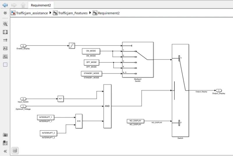
The subsystem “Requirement2” takes the output from “Requirement1” as one of the inputs along with inpus “Input_Switch & Enable_Display”.
The input “Enable_Display” is saturated using ‘Saturation’ block and given to condition input of a ‘Multi-port Switch’ block.
“On_mode, Off_mode & Standby_mode” are given as the other inputs of multi-port switch.
Output from ‘Multi-port switch’ is given to true side of a ‘Switch’ block and the false side with “No_Display” constant block.
“Input_Switch” block is given as input to “AND” block via a “NOT” block.
“Optimum_Voltage” is given as second input to the “AND” block.
“Interrupt1 & Interrupt2” are 2 constant blocks checked for “equality” and given as conditional threshold to the switch.
The output of the switch is taken as “Output_display” which is the entire model output.
Then the created SLDD file is linked with the model & run.
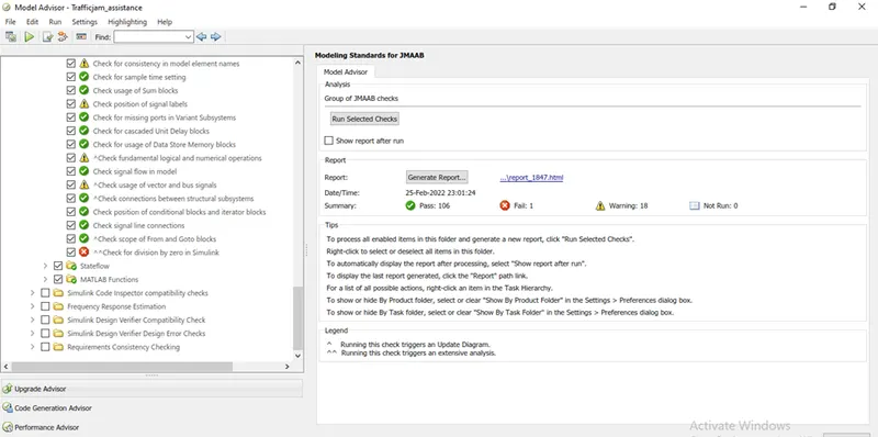
Then “Model Advisor” check is done.
The code generation is done as follows:
> open configuration parameter -> Code generation -> select system start file (ert.tlc) ->Select tool chain (Automatically locate an installed toolchain) ->Apply ->Ok.
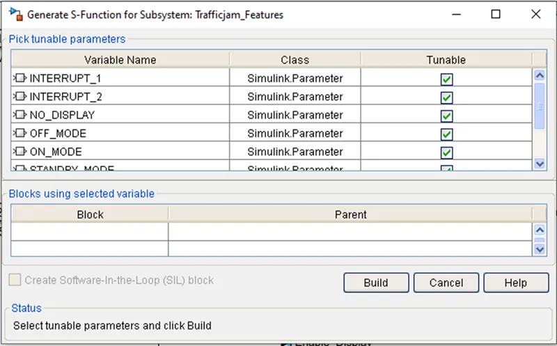
>Select & Right click the subsystem -> create C,C++ -> generate S-function .
>Generate S-function for subsystem dialogue box opens -> Enable create Software in Loop block -> build.
> “System_ert_rwt” folder is created with generated C files, this folder is attached.
Results:
Thus the following tasks are performed:
- This model must be developed in MATLAB Simulink as per MBD guidelines.
- Code Generation Profile must be in Embedded Coder.
- Simulink Data Dictionary must be created for the model & must be linked to the model.
- Model Advisor Report is mandatory & this will be followed by Code Generation