Week-6 Challenge: EV Drivetrain
Q1 Which types of power converter circuits are employed in electric and hybrid electric vehicle?
>>The different types power converter circuits are
>>In an Electrical vehicle or hybrid Electrical vehicle, the DC input from battery, supercapacitor or fuel cell of different voltage rating are individually converted to the required voltage. Here a DC- DC step up or DC-DC step down converters are used.
>>Variable DC to constant DC are used.
>>A DC-link is generally used to link the DC input from different sources and given as a single input to the next level of the system.
>>The DC source is converter to AC source with the help on an AC – DC converter.
>>An AC- DC converter is used before the battery, when the battery is charged by an AC supply.
>>Namely the power converters in Electrical vehicle & hybrid Electrical vehicle are
1.Rectifiers
2.Choppers
3.Converters such as inductors, capacitors & transformer.
Q2. An Electric Vehicle's powertrain with 72V battery pack in shown in the diagram below. The duty ratio for acceleration operation is 'd1' and for the braking operation the duty ratio is 'd2'
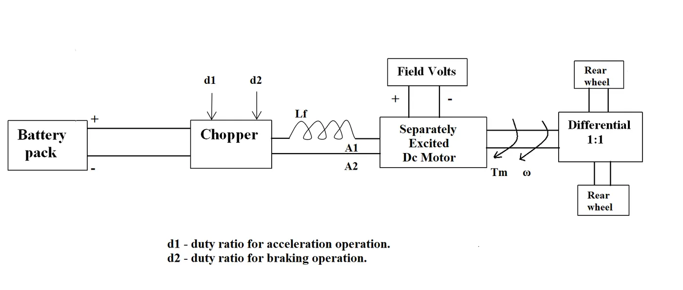
The other parameters of the electric vehicle is given below,
Motor and Controller Parameters:
Rated Armature voltage= 72 V
Rated armature current= 400 A
Ra= 0.5Ω, KΦ= 0.7 Volt second
Chopper Switching frequency= 400 Hz
The vehicle speed-torque characteristics are given by the below equation
What is EV steady state speed if duty cycle is 70%?
Given:
Rated Armature voltage (Va)= 72 V
Rated Armature Current (Ia) = 400 A
Armature resistance (Ra) = 0.5 ohms
K ɸ = 0.7 V/s
Chopper switching frequency = 400 Hz
Duty cycle = 70% = 0.7
Solution:
Actual Voltage = 72*0.7 = 50.4
Vehicle Speed-Torque characteristics (Tv) = 24.7 + (0.0051)( Ꞷ^2)-------------1
Motor torque (Tm) = [(V*(Kɸ)/Ra) – ((Kɸ)^2)/Ra)] * Ꞷ
Tm =[((50.4*0.7)/0.5) – ((0.7)^2)/0.5)] * Ꞷ
Tm = 70.56 – 0.98 Ꞷ ------------2
Equating Eq 1 & 2
24.7 + (0.0051)( Ꞷ^2) = 70.56 – 0.98 Ꞷ
(0.0051)(Ꞷ^2) + 0.98 Ꞷ - 45.86 = 0
Ꞷ = 38.915 rad/sec , -231.072 rad/sec
Q3 Develop a mathematical model of a DC Motor for the below equation using Simulink.
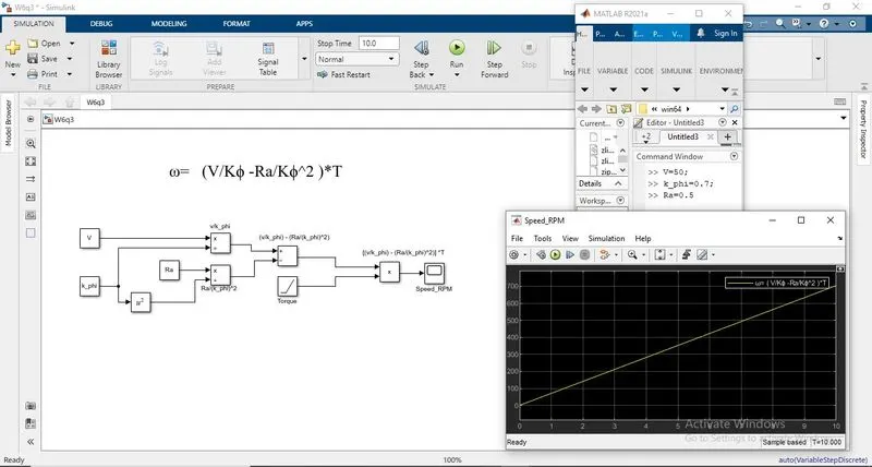
ω= (V/Kϕ -Ra/Kϕ^2 )*T
>>Constants V & Kϕ are taken.
>>V is divided by Kϕ using a divide block with ‘*/’ operation.
>>A square block is taken Kϕ is squared.
>>Constant Ra is divided by square of Kϕ using a divide block with ‘*/’ operation.
>>Both the outputs are subtracted using ‘subtraction’ block.
>>And its output is multiplied with a ramp block which is considered as input Torque in Nm.
>>The output from multiplication block is given to a scope displaying he speed value with respect to the input torque given.
>>Then the constants are defined in the workspace as follows:
*V = 50 V
*K_phi = 0.7
*Ra = 0.5 ohms
>>And the model is run.
>>The resultant scope is attached below.
Q4. Refer to the blog on below topic:
Induction Versus DC brushless motors by Wally Rippel, Tesla
Explain in brief about author’s perspective.
The blog is written by Wally Ripple, Principal power electronics engineer and published on January 9, 2007.
Initially he discusses about brushless machines, saying “The brushless machines have 2 or more permanent magnets generating DC magnetic field. This DC magnetic field when interacts with current flowing stator produces a torque interacting between the rotor & stator. As the rotor rotates, the magnitude & polarity of the stator current continuously varies keeping the torque constant which an optimal efficiency and I produces no starting torque when directly connected to fixed frequency utility power.” He also adds that the brushless motors are useless without the current control device called ‘inverter’.
On moving to the induction motor, he author says that the stator of an induction motor is same as DC brushless motor but the stator has 3 sets of distributed windings inserted within the stator core. The rotor construction size completely varies with stacked steel laminations buried peripheral conductors that form a “shorted structure.” Current flowing in the stator windings produces a rotating magnetic field that enters the rotor and the frequency of this magnetic field in rotor is equal to its difference between the applied electrical frequency and the rotational frequency. An induced voltage across the short structure is proportional to the speed difference between the rotor and electrical frequency. In response to this voltage, current are produced within the rotor conductors that are approximately proportionate to the voltage resulting in speed variation. A desired torque is produced when the current interacts with magnetic field producing force. He adds that the induction motor can work without an inverter unless a brushless motor. The only main difference brushless and induction motor are control code and the brushless DC motor get less heated than the induction motor at peak torque.
He also concludes saying that the DC brushless motor will dominate the hybrid and plug-in hybrid market as its peak efficiency is comparatively higher even when the loss increases as its size increases. The induction motor is said to have comparatively peak efficiency even when the loss isn’t influenced by its increase in size.