Final Project: Design of an Electric Vehicle
AIM:
To create a MATLAB model of electric car which uses a battery and a DC motor. Choose suitable blocks from Powertrain block set and prepare a report about the model.
OBJECTIVE:
1. System level configurations
2. Model parameters
3. Results
4. Conclusion
ELECTRICAL VEHICLE:
Electrical vehicle are vehicles powered by electric power. Electrical vehicle are environment friendly as no fossil fuel is being used. Electrical vehicle have low running cost as it has less moving parts. The types of Electrical vehicle are pure Electrical vehicles or hybrid electrical vehicle. Highly efficient Electrical vehicle could be reached with help technological advancements in semiconductor devices & motor control. Electrical vehicle are dependent source of transportation in the near future.
COMPONENTS OF ELECTRICAL VEHICLE:
A pure electrical vehicle is consists of the following components:
Battery
Power Converter
Motor controller
Motor
Transmission
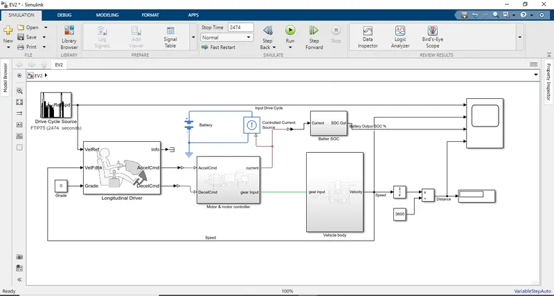
The system level configuration for Electrical vehicles are done as follows:
1.Drive cycle source & driver
- Battery pack & power converters
- Motor & motor controller
- Vehicle body
The above systems are put together to form the Electrical vehicle system on MATLAB Simulink and are discussed briefly.
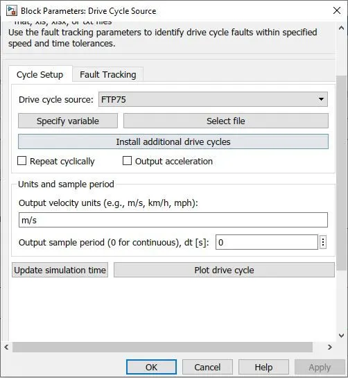
DRIVE CYCLE SOURCE
Drive cycle is pre-determined data that represents the running pattern of the vehicle.
>>Here we are choosing the drive cycle ‘FTP75’
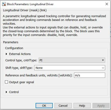
LONGITUDINAL DRIVER:
The block ‘Longitudinal driver’ is used to create a longitudinal speed tracking control.
>>The Drive cycle is fed into the velocity reference (VelRef)
>>Velocity feedback is fed with the final velocity from the vehicle body.
>>The acceleration command (AccleCmd) & deceleration command (DecelCmd) are given to motor controller block.
>>The block’s parameter settings are shown below.
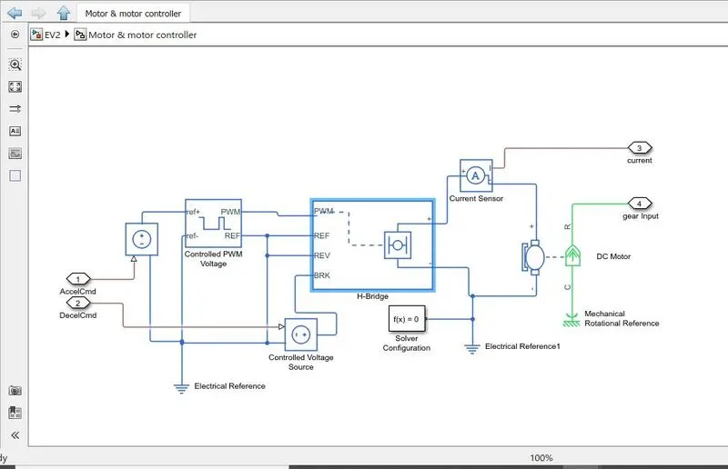
MOTOR CONTROLLER
Motor controller unit is designed to control the speed of the motor using a voltage signal with respect to input drive cycle data.
>>The motor control is done with the help of ‘H-Bridge’ & a ‘Controlled PWM Controller’
>>The acceleration & deceleration command from the longitudinal driven taken as input in his subsystem.
>>The ‘Controlled voltage source’ receives the acceleration & deceleration command.
1.Controlled PWM Controller:
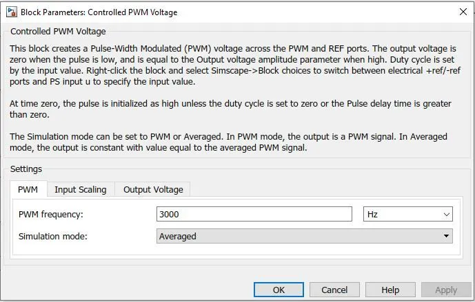
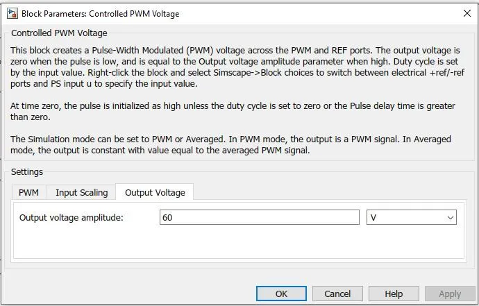
PWM frequency is set as 3000Hz and ‘Averaged’ simulation mode is set as shown below.
>> The acceleration command is given to the ‘ref+’ via the ‘controlled voltage source’ block’
>>The reference block from the controlled voltage source, Controlled PWM Controller & H-Bridge controller are shorted and given to an ‘electrical reference’ & ‘solver configuration’ blocks .
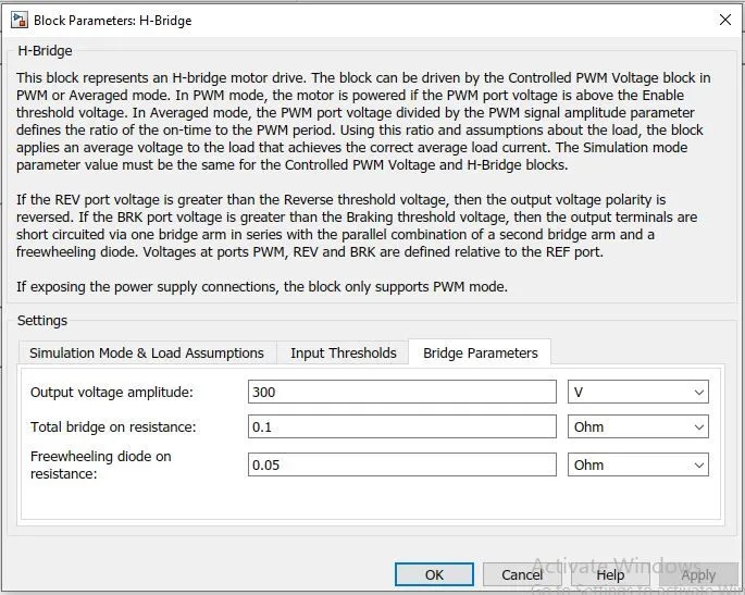
2.H-Bridge block:
The polarity of the voltage applied across the ‘DC Motor’ is changed using this block. This helps the motor to run in forward & reverse direction.
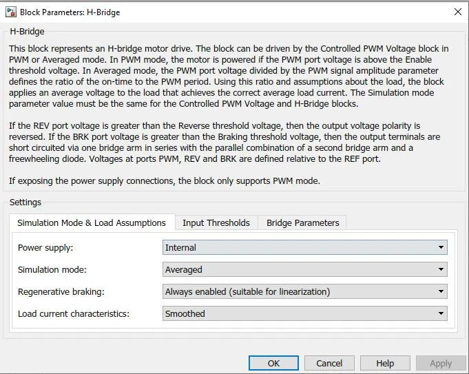
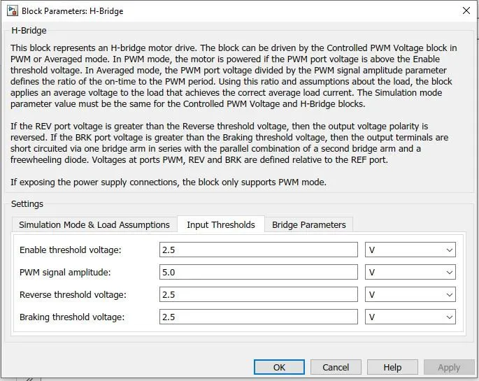
>>The simulation mode, load assumptions, input threshold & bridge parameters are set as shown in the picture below.
>>The output from the ‘H-Bridge’ block is given to the DC-Motor block and the motor input current is measured using a current sensor
3.DC Motor:
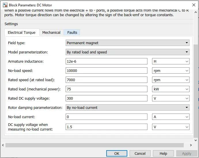
The DC Motor block is used to convert the electrical input to mechanical output and move the vehicle.
>> DC Motor also acts as generator while braking making it regenerative braking.
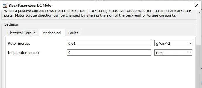
>>The electric torque & mechanical parameters are set as shown below.
BATTERY
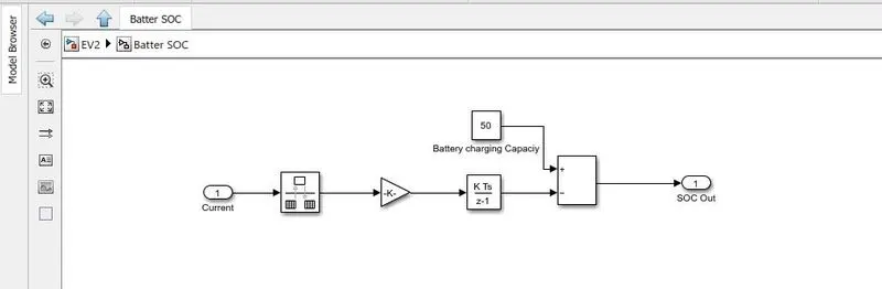
A battery block is created with a battery connected parallel with the current sensor representing the battery pack in vehicle.
>>A nominal voltage of 300V is set.
>>The current output from the battery pack is given to a system of ‘Rate transition’, gain and ‘discrete time integrator’ giving the SOC of the battery.
VEHICLE BLOCK:
GEAR:
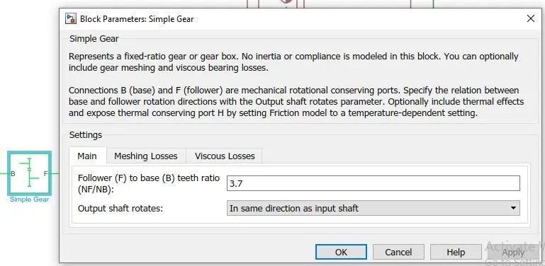
The input to the vehicle block is given to the simple gear, its ratio is set as 3.7 and its output is given to the rear tire axle via a shaft inertia block whose inertia is 0.01.
TIRE:
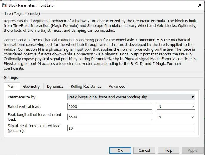
Tires are represented by ‘Tire(Magic formula)’ blocks, 4 tires represent 4 wheels in the vehicle.
>>The 4 tires are arranged in as 2 front & 2 rear tires.
>>Tire parameters such as nominal load capacity, rolling resistance, dynamics & geometry are defines as shown in the pictures below.
>>The ‘N’ of the rear tires & front tires are connected to NR &NF of the vehicle body respectively.
>>The ‘H’ all the tires are connected to ‘H’ of the vehicle body.
>>The ‘S’ in all the tires are connected to terminators.
>>The ‘A’ of front tires are shorted and that of rear tires are shorted and given to gear output ‘F’.
VEHICLE BLOCK
Vehicle block represent the vehicle body along with the chasis with tires and the gear. It is built using the following blocks:
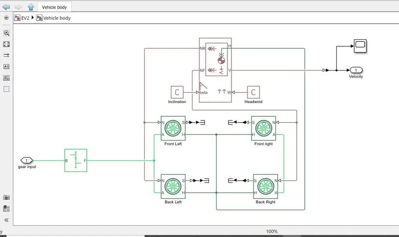
>>‘Vehicle body’ block has 2 input ports, 3 output ports and a connector port (H)
>>Wind velocity (W) and grade angle (beta) are the input ports.
>> Normal force on rear axle (NR) & Normal force on front axle (NF) are the output ports connected to ‘N’ of rear & front tire pairs.
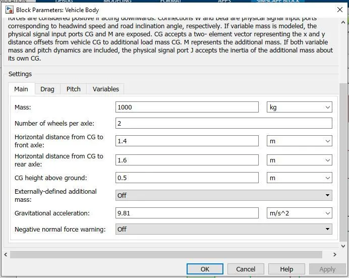
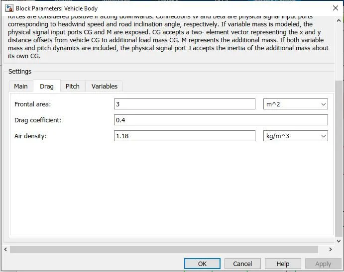
>>In ‘Vehicle body’ block, parameters such as mass, drag coefficient, air density, pitch and other variables are set and are shown the pictures below.
>> Velocity (v) is taken as output and integrated to get the distance travelled by the vehicle.
SCOPE:
The parameters connected to the scope are:
>>The drive cycle
>>Battery SOC
>>Speed
>>Distance
RESULT:
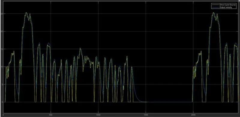
>>The first graph shows the FTP75 drive cycle for 2474 seconds and the speed travelled by the Electric vehicle
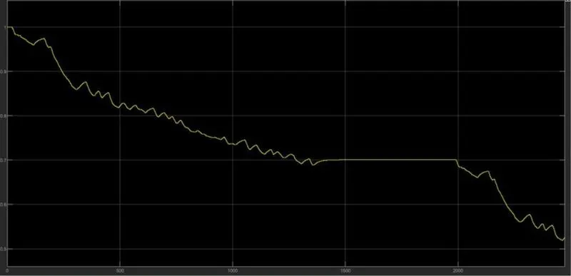
>> The second graph shows the battery SOC
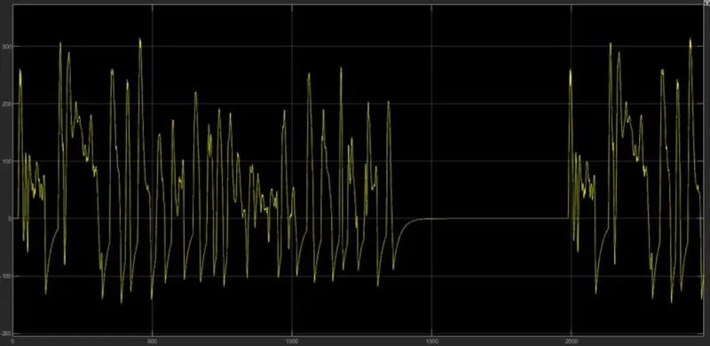
>> The third graph shows the distance in which the vehicle has travelled in the given period of time and the display, displays the overall distance travelled by the vehicle and the total distance travelled is 20.48 Km.
CONCLUSION:
Thus a MATLAB model of electric car using a battery, a DC motor and suitable Powertrain block set are created along with system configuration, model parameters, results & conclusion.