Project 2-Highway Assistant-Lane Changing Assistant
AIM:
To prepare the following:
- This model must be developed in MATLAB Simulink per MBD guidelines.
- Code Generation Profile must be Autosar Coder.
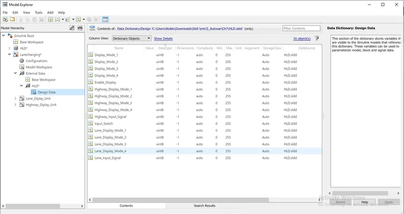
- Simulink Data Dictionary must be created for the model & must be linked to the model.
- All the input & output signals must be mapped into the Autosar Editor.
- Model Advisor Report is mandatory & this will be followed by Code Generation.
Modelling;
Input Signals:
|
Name of the Signal |
Data Type |
Range |
|
Highway_Input_Signal |
uint8 |
0 - 255 |
|
Enable_Display |
uint8 |
0 – 255 |
|
Input_Switch |
uint8 |
0 – 255 |
|
Lane_Input_Signal |
uint8 |
0 - 255 |
Local Signals:
|
Name of the Signal |
Data Type |
Range |
|
Highway_Display_Mode_1 |
uint8 |
0 - 255 |
|
Highway_Display_Mode_2 |
uint8 |
0 – 255 |
|
Highway_Display_Mode_3 |
uint8 |
0 – 255 |
|
Highway_Display_Mode_4 |
uint8 |
0 – 255 |
|
Lane_Display_Mode_1 |
uint8 |
0 – 255 |
|
Lane_Display_Mode_2 |
uint8 |
0 – 255 |
|
Lane_Display_Mode_3 |
uint8 |
0 – 255 |
|
Lane_Display_Mode_4 |
uint8 |
0 – 255 |
Output Signals:
|
Name of the Signal |
Data Type |
Range |
|
Display_Mode_1 |
uint8 |
0 - 255 |
|
Display_Mode_2 |
uint8 |
0 – 255 |
|
Display_Mode_3 |
uint8 |
0 – 255 |
|
Display_Mode_4 |
uint8 |
0 - 255 |
A SLDD file with given data is developed:
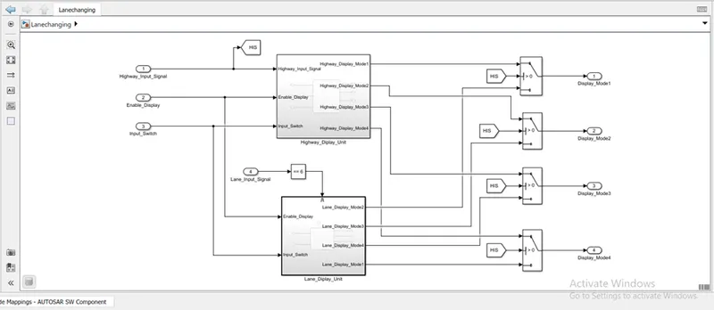
The entire model is modelled a shown below:
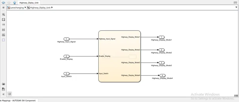
Requirement No 1 [Highway_DisplayUnit]:
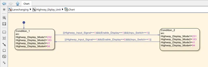
Inputs to this particular subsystem are “Highway_Input_Signal”, “Enable_Display”, “Input_Switch”. These three input signals, when assigned to a particular value will give output signals of specific value. The output signals are “Highway_Display_Mode_1”, “Highway_Display_Mode_2”, “Highway_Display_Mode_3”, “Highway_Display_Mode_4”. The requirement must be implemented in the form of a Stateflow logic.
|
Condition |
Action |
|
Highway_Input_Signal = 1 Enable_Display = off Input_Switch = on |
Highway_Display_Mode_1 = 232 Highway_Display_Mode_2 = 183 Highway_Display_Mode_3 = 41 Highway_Display_Mode_4 = 94 |
|
Highway_Input_Signal = 1 Enable_Display = on Input_Switch = on |
Highway_Display_Mode_1 = 213 Highway_Display_Mode_2 = 183 Highway_Display_Mode_3 = 9 Highway_Display_Mode_4 = 94 |
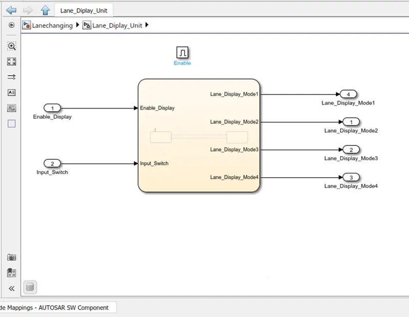
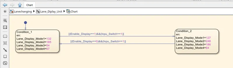
Requirement No 2 [Lane_DisplayUnit]:
Inputs to this particular subsystem are “Enable_Display”, “Input_Switch”, “Lane_Input_Signal”. These three input signals, when assigned to a particular value will give output signals of specific value. The output signals are “Lane_Display_Mode_1”, “Lane_Display_Mode_2”, “Lane_Display_Mode_3”, “Lane_Display_Mode_4”. The requirement must be implemented in the form of Stateflow logic.
|
Condition |
Action |
|
Lane_Input_Signal= 6 Enable_Display = off Input_Switch = on |
Lane_Display_Mode_1 = 132 Lane_Display_Mode_2 = 185 Lane_Display_Mode_3 = 54 Lane_Display_Mode_4 = 67 |
|
Lane_Input_Signal= 6 Enable_Display = on Input_Switch = on |
Lane_Display_Mode_1 = 127 Lane_Display_Mode_2 = 248 Lane_Display_Mode_3 = 186 Lane_Display_Mode_4 = 84 |
Requirement No 3:
Signals coming from both subsystems “Highway_Display_Mode_1” & “Lane_Display_Mode_1” are given as inputs to a switch block which will have input signal “Highway_Input_Signal” given as 2nd input to the switch block. Corresponding output from this particular switch block is output signal “Display_Mode_1”.
Signals coming from both subsystems “Highway_Display_Mode_2” & “Lane_Display_Mode_2” are given as inputs to a switch block which will have input signal “Highway_Input_Signal” given as 2nd input to the switch block. Corresponding output from this particular switch block is output signal “Display_Mode_2”.
Signals coming from both subsystems “Highway_Display_Mode_3” & “Lane_Display_Mode_3” are given as inputs to a switch block which will have input signal “Highway_Input_Signal” given as 2nd input to the switch block. Corresponding output from this particular switch block is output signal “Display_Mode_3”.
Signals coming from both subsystems “Highway_Display_Mode_4” & “Lane_Display_Mode_4” are given as inputs to a switch block which will have input signal “Highway_Input_Signal” given as 2nd input to the switch block. Corresponding output from this particular switch block is output signal “Display_Mode_4”.
Then the created SLDD file is linked with the model & run.
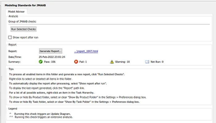
Then “Model Advisor” check is done.
The code generation is done as follows:
> open configuration parameter -> Code generation -> select system start file (ert.tlc) ->Select tool chain (Automatically locate an installed toolchain) ->Apply ->Ok.
>Select & Right click the subsystem -> create C,C++ -> generate S-function .
>Generate S-function for subsystem dialogue box opens -> Enable create Software in Loop block -> build.
> “System_ert_rwt” folder is created with generated C files, this folder is attached.
RESULT:
Thus the given tasks are done successfully, they are:
- This model must be developed in MATLAB Simulink per MBD guidelines.
- Code Generation Profile must be Autosar Coder.
- Simulink Data Dictionary must be created for the model & must be linked to the model.
- All the input & output signals must be mapped into the Autosar Editor.
- Model Advisor Report is mandatory & this will be followed by Code Generation.